


Truck drive shafts are the unsung heroes of heavy-duty logistics, tasked with transmitting immense power while surviving constant structural stress. This analysis delves into the components, load dynamics, and material optimizations that define modern truck drivetrain engineering.

1. Key Components and Their Structural Roles
A drive shaft is more than a single pipe; it is a sophisticated assembly of three core elements designed for durability and flexibility.
- The Shaft Tube: The primary structural element. Using a hollow tubular design in high-strength alloy steel or Aluminum Alloy 6061, it balances torsional rigidity with weight. Aluminum variants can reduce mass by 30% while maintaining commercial-grade tensile strength.
- The Telescopic Sleeve: This allows for distance adjustments between the transmission and the drive axle during suspension travel. Modern sleeves use nylon-coated spline teeth to minimize wear and reduce impact loads.
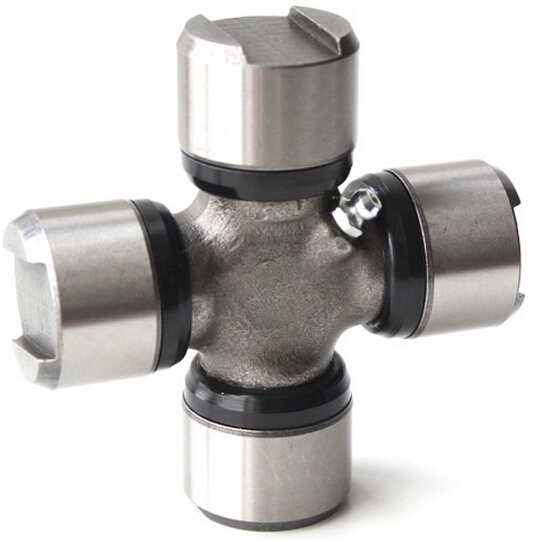
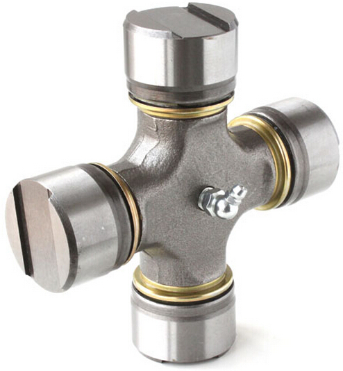
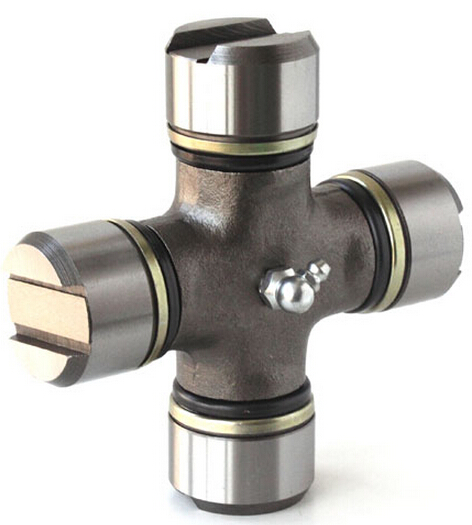
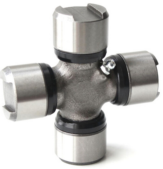
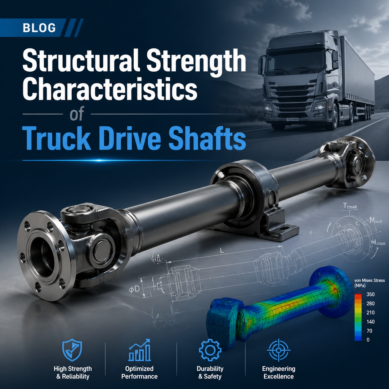
- Universal Joints: The most critical stress points. These cross-axis designs allow for angular movement. Under peak torque, stress peaks at 168–169 MPa, requiring 20Cr alloy steel with a yield strength of 540 MPa to maintain a safety factor above 3.0.
2. Load Distribution Under Dynamic Conditions
Drive shafts don’t just spin; they endure a complex cocktail of torsion, bending, and axial forces.
Stress Concentration and Failure Modes
When traversing uneven terrain, universal joints must manage angles up to 15°. This movement creates a non-uniform stress distribution:
- Universal Joints: Experience 2.6 to 3.2 times higher stress concentrations than the shaft tube.
- Spline Engagement: Must withstand shear forces exceeding 50 kN during sudden torque surges.
- Primary Failure Mode: In heavy trucks, failure usually begins with plastic deformation of the cross-axis bearing housing rather than a fracture of the main tube.
Vibration and Balance
Improper balancing can be catastrophic, reducing critical rotational speed by 40%.
Standard: Manufacturers precision-balance components to within 0.5 oz-in (3.5 g-cm) and use specialized damping materials to suppress high-frequency oscillations.
3. Material Selection and Optimization Strategies
Engineers utilize a “dual-material” approach to maximize the strengths of different alloys.
Material Specifications
| Component | Material | Treatment/Feature |
| Cross-Axis | 20CrMo Alloy Steel | Carburized to 58-62 HRC surface hardness. |
| Shaft Tube (Al) | 6061-T6 Aluminum | Fatigue limit of 90 MPa; high corrosion resistance. |
| Shaft Tube (St) | High-Strength Steel | Fatigue limit of 180 MPa for heavy-duty apps. |
Structural Optimization Techniques
- Geometric Modification: Fillet radii at component transitions are optimized to 3–5mm to minimize stress peaks.
- Gradient Thickness: Some tubes increase wall thickness by 20% near the universal joint attachments to provide localized stiffness.
- Advanced Manufacturing: * Friction Welding: Increases joint strength by 35% for hybrid steel-aluminum shafts.
- Laser Cladding: Extends spline tooth life by 2–3x using wear-resistant coatings.
Engineering Summary
Modern drive shafts are engineered to withstand peak torques exceeding 10,000 N·m and are rated for service intervals over 500,000 km. Through the combination of Finite Element Analysis (FEA) and innovative material science, these components ensure that heavy-duty trucks remain reliable under the most grueling commercial conditions.
Is your fleet experiencing premature drivetrain wear or unexplained vibrations?
Our engineering team specializes in drive shaft structural optimization and custom material selection tailored to your specific operational needs. Click here to contact our Engineering Consultants today for a deep-dive solution that maximizes uptime and minimizes your total cost of ownership!