


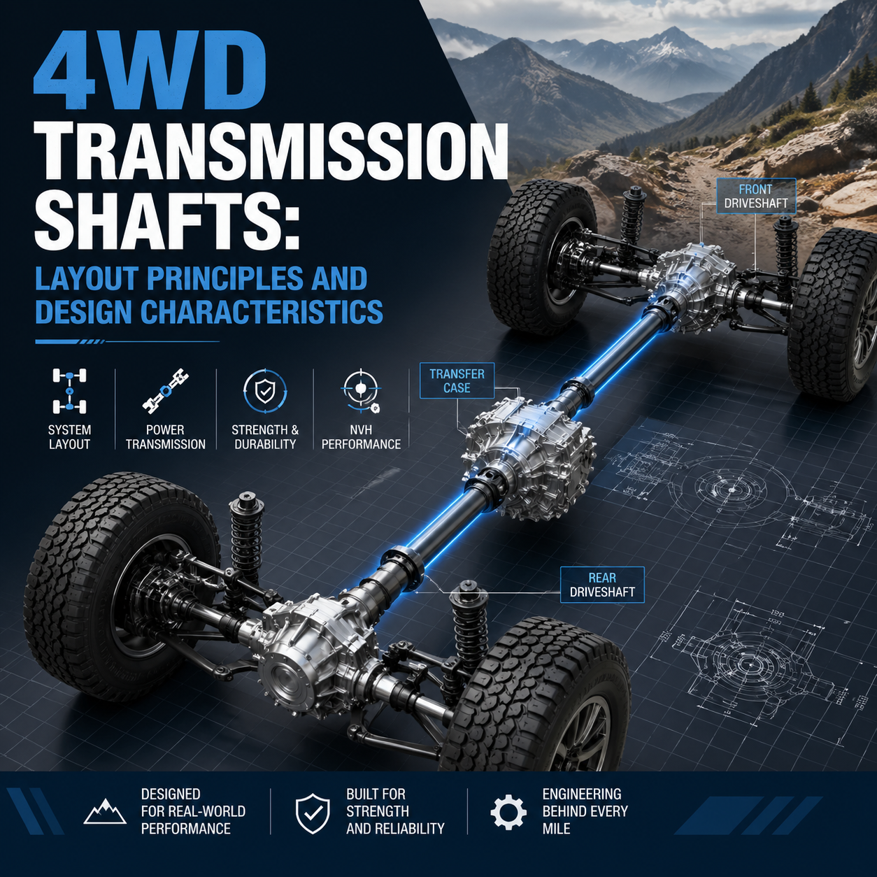
The transmission shaft is the critical link in a Four-Wheel Drive (4WD) system, responsible for distributing torque across different axles under varying load conditions. Understanding how these shafts are laid out and designed is essential for grasping modern vehicle dynamics.

1. Primary Layout Forms of 4WD Systems
The physical arrangement of a 4WD system is dictated primarily by the engine’s orientation.
Longitudinal FR-based 4WD
Derived from Front-Engine, Rear-Wheel Drive platforms, these systems add a transfer case to the rear of the transmission.
- Mechanism: Power is split, sending one shaft to the rear and an additional shaft forward to the front axle.
- Benefit: Retains classic rear-drive handling while drastically improving off-road traction.
Transverse FF-based 4WD
Common in compact SUVs and crossovers, this layout begins with a Front-Engine, Front-Wheel Drive setup.
- Mechanism: A right-angle gear set (Power Take-off Unit) redirects power from the transverse engine toward the rear axle.
- Benefit: Efficient space utilization, though it presents compact packaging challenges.

RR-based 4WD
Primarily seen in high-performance sports cars.
- Mechanism: Power is sent forward from the rear engine through a central tunnel to a front differential.
- Benefit: Optimizes weight distribution for high-speed cornering.
2. Structural Design Requirements
Because 4WD vehicles often operate on uneven terrain, their shafts must handle “multi-angle” operations without losing efficiency.
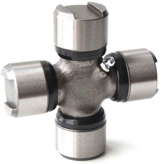
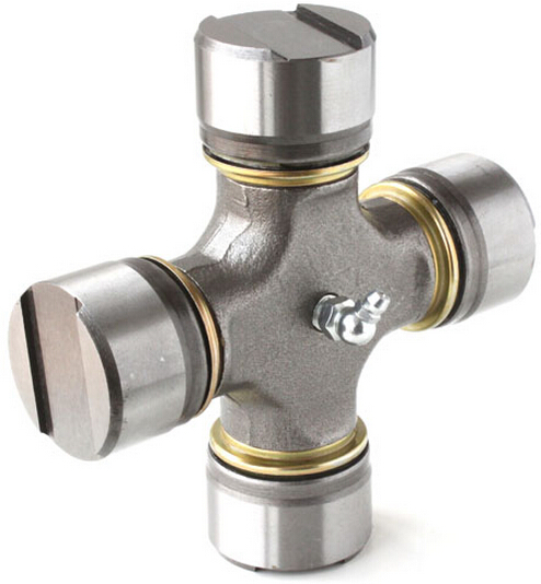
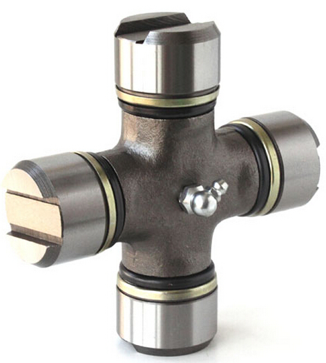
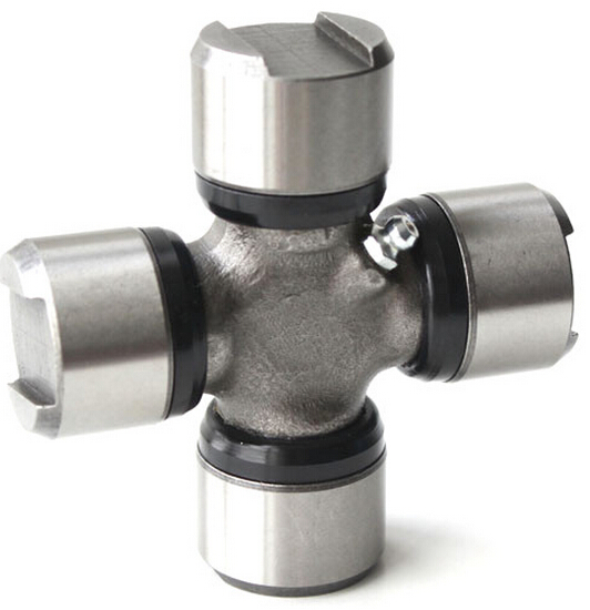
- Joint Integration: Universal Joints (U-Joints): Allow for basic angular movement between connected shafts.
- Constant-Velocity (CV) Joints: Ensure the output shaft rotates at the exact same speed as the input shaft, regardless of the angle. Rzeppa-type CV joints are the industry standard for front axles due to their stability during steering maneuvers.
- Material Fatigue: Shafts are typically crafted from high-strength alloys. High-performance models often utilize hollow shafts to shave off unsprung weight without compromising torsional rigidity.
3. Angle Management and Dynamic Adjustment
Longevity in a 4WD system is almost entirely dependent on managing the angles at which the shafts operate.
Operating Angle Thresholds
Excessive angles lead to accelerated wear and parasitic power loss. In a standard longitudinal setup, engineers aim for the following:
- Normal Operation: Below 3°.
- Maximum Threshold: 7° (Exceeding this typically triggers noticeable vibration and resonance).
Adaptive Features
| Feature | Function | Application |
| Sliding Splines | Allows the shaft to change length dynamically. | Essential for vehicles with high suspension travel. |
| Electronic Sensors | Monitors drivetrain angles in real-time. | Used by modern ECUs to adjust torque distribution. |
| Telescoping Sections | Maintains proper tension under load changes. | Found in heavy-duty off-road applications. |
4. The Role of Modern Electronics
Modern 4WD systems are no longer purely mechanical. Integration with electronic control systems allows the vehicle to monitor stress on individual transmission components. By adjusting torque distribution on the fly, the system reduces the instantaneous stress on the transmission shafts, effectively extending the component life and improving fuel economy.
🛠️ Need Technical Support for Your Drivetrain?
Are you experiencing driveline vibrations or designing a custom 4WD layout?
Our engineering team specializes in drivetrain optimization and angle management solutions. Click here to consult with our Technical Team for professional guidance on shaft selection, vibration analysis, and torque distribution strategies!