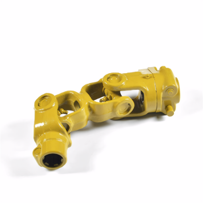
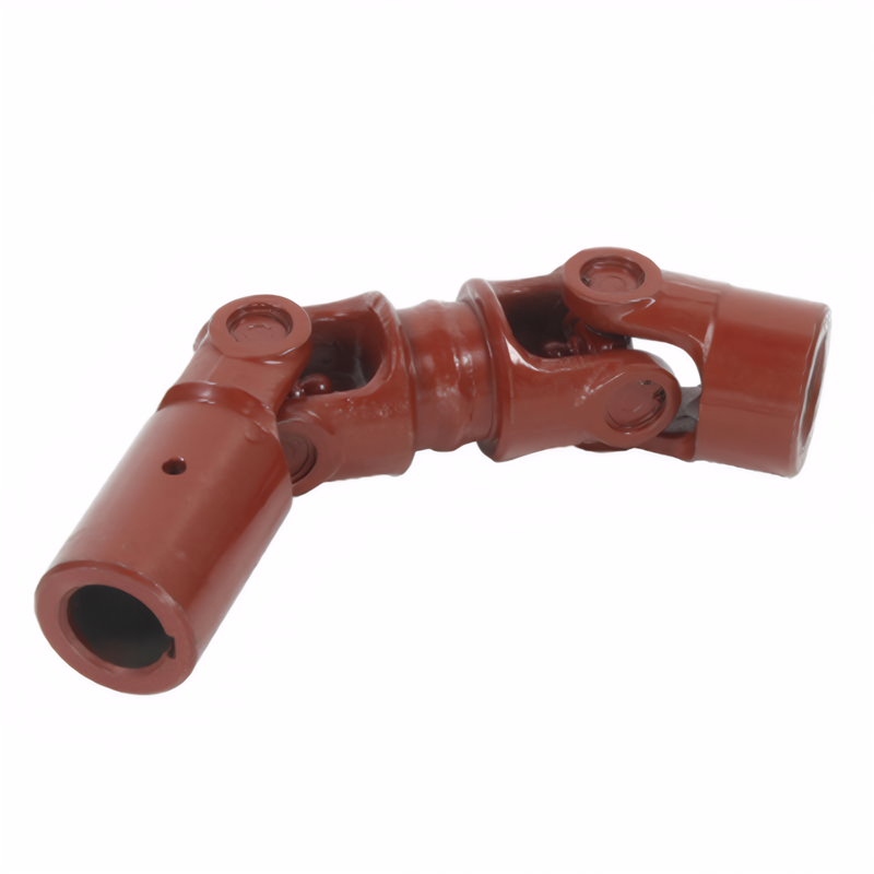
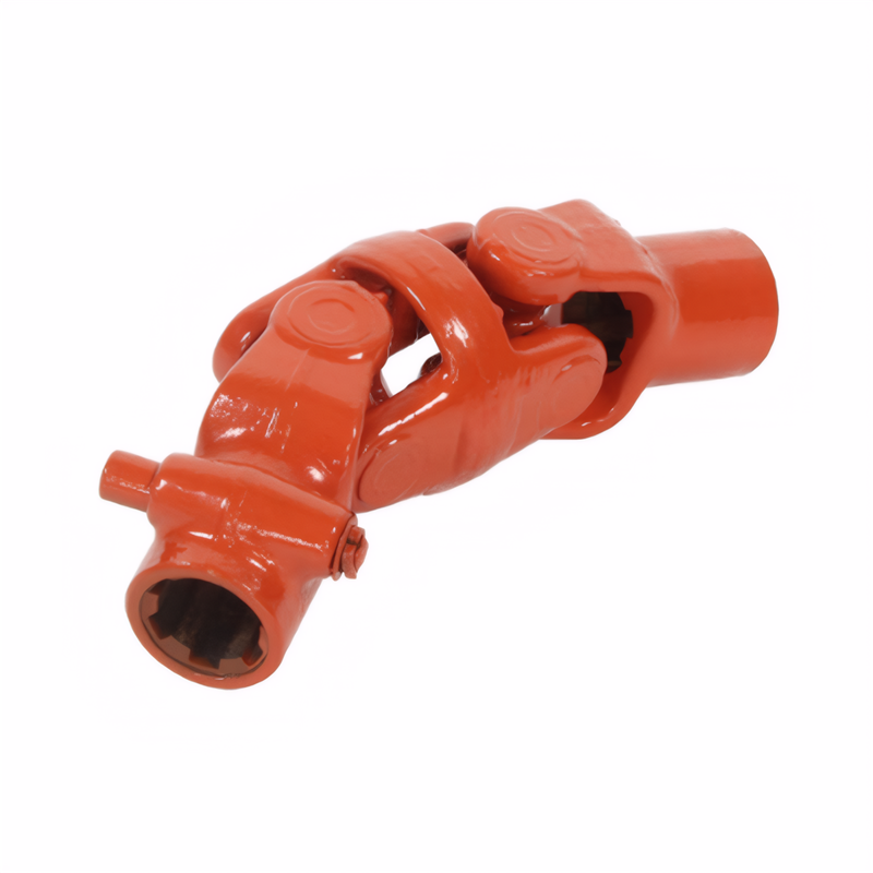
The ability of the drive shaft to adapt to changes in Angle
Angular Adaptability Capabilities of Drive Shafts in Automotive Applications
Mechanical Design Features Enabling Angular Movement
Drive shafts achieve angular adaptability through specialized joint systems that maintain rotational continuity during suspension travel. The most common solution involves universal joints (U-joints) with needle roller bearings housed in forged steel yokes. These joints allow angular displacements up to 25° in passenger vehicles and 30° in heavy-duty applications by permitting rotational axis variation between connected components.
Constant-velocity (CV) joints represent an advanced evolution, employing ball-and-groove mechanisms to eliminate speed variations during angular movement. Double-offset CV joints enable operational angles exceeding 45° while maintaining constant rotational speed, crucial for front-wheel-drive vehicles with independent suspension systems. The ball tracks in these joints feature precision-ground surfaces with 2-3 micron tolerances to ensure smooth power transmission.
Hybrid designs combining U-joints with CV elements appear in specialized applications. These systems use a U-joint at the transmission end for cost efficiency and a CV joint at the differential end to handle larger angular variations. The transition zone between joint types incorporates flexible boots filled with high-viscosity grease to prevent contaminant ingress while accommodating 15-20° of cumulative angular movement.
Material Science Contributions to Flexibility
The angular adaptability of drive shafts relies heavily on material properties at component interfaces. Universal joint crosses made from 20CrMnTi alloy steel undergo carburizing treatment to create a 1.2mm case-hardened layer with 58-62 HRC surface hardness. This treatment maintains core toughness while preventing wear at bearing contact surfaces during repeated angular articulation.
Needle roller bearings within U-joints use high-carbon chromium steel (GCr15) with precision grinding to achieve 0.5-micron surface roughness. The smooth finish reduces friction coefficient by 30% compared to standard bearings, enabling smoother angular movement under load. Some designs incorporate ceramic-coated needles to further reduce friction in high-temperature environments.
CV joint ball cages employ sintered metal or composite materials with self-lubricating properties. These materials contain embedded solid lubricants like molybdenum disulfide that migrate to contact surfaces during operation, forming a protective layer that reduces wear rates by 50% during extreme angular movement. The ball cage geometry is optimized through finite element analysis to distribute loads evenly across all contact points.
Performance Optimization Through Geometric Configuration
The angular capacity of drive shafts depends on precise geometric relationships between components. U-joint operating angles follow the "double-cardan" principle where the sum of input and output angles should not exceed 6° to prevent speed fluctuations. This limitation necessitates careful alignment during installation, with laser alignment tools ensuring angular precision within ±0.5°.
CV joint design incorporates specific ball track radii that determine maximum operating angle. For example, a 120mm track radius enables 45° articulation while maintaining contact pressure below 500 MPa. The groove profile follows an elliptical arc to prevent ball dislocation during extreme angles, with transition radii optimized to reduce stress concentrations by 40% compared to circular profiles.
In multi-piece drive shaft systems, intermediate support bearings play a critical role in angular adaptability. These bearings use preloaded tapered roller elements to accommodate 2-3° of misalignment without inducing axial loads. The bearing housing incorporates elastomeric mounts that flex to absorb angular variations, reducing stress transmission to the shaft tube by 65% during suspension compression.
 The inspection method for the
 Symptoms of wear of the univer
 Analysis of the Causes of Abno
 The ability of the drive shaft
 简体中文
简体中文 English
