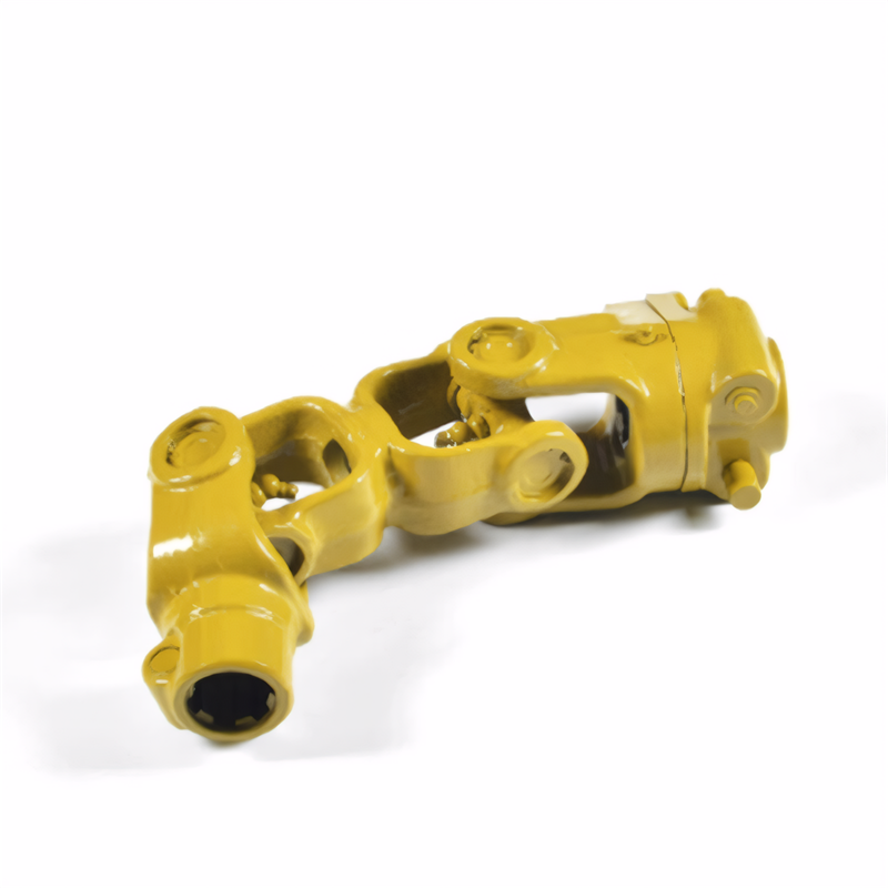
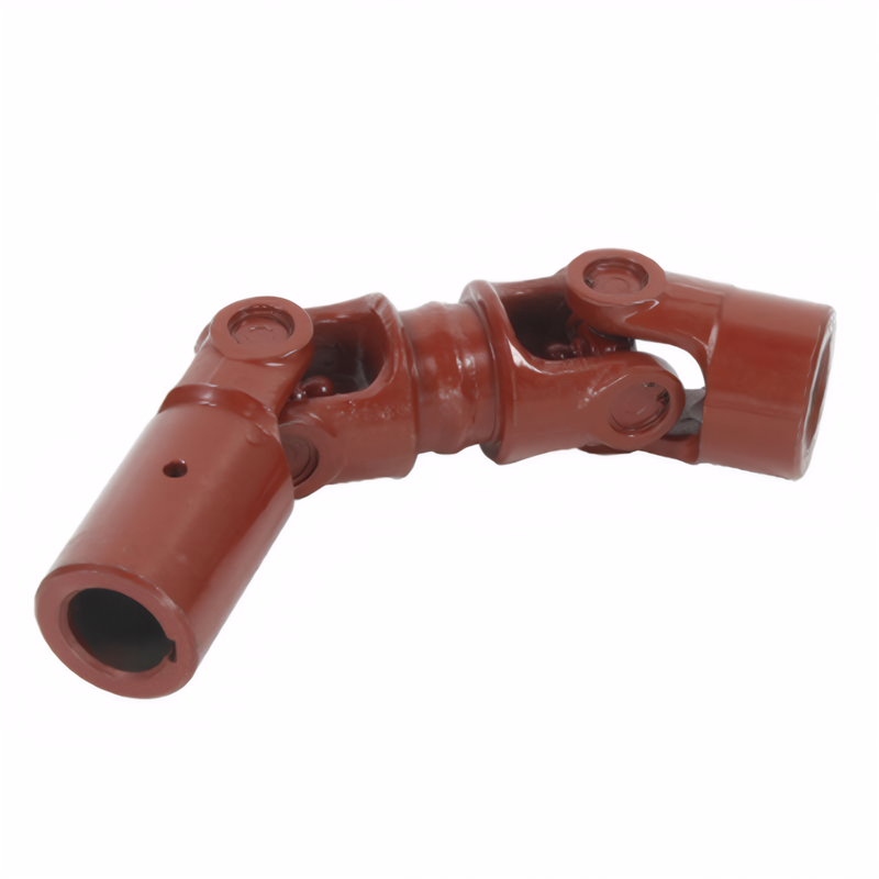
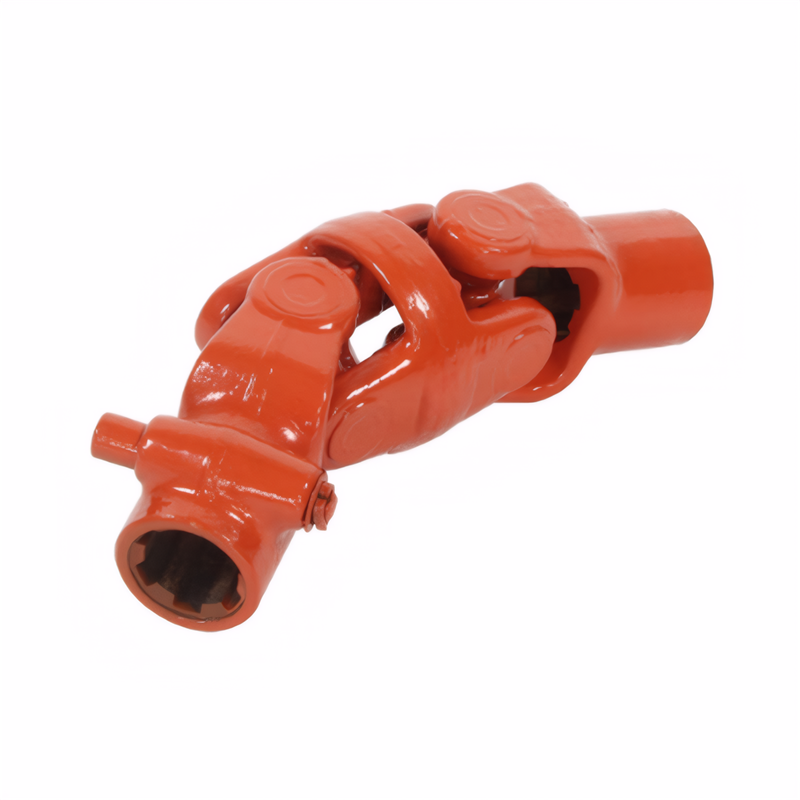
The installation position of the balance plate of the drive shaft
Installation Positions of Balance Weights on Drive Shafts
Functional Requirements Driving Balance Weight Placement
Drive shafts operate under rotational speeds exceeding 5,000 RPM in automotive applications, generating significant centrifugal forces that amplify minor mass imbalances. Balance weights are strategically positioned to counteract these forces through precise mass distribution. The primary installation area lies along the cylindrical surface of the drive shaft tube, where weights are welded or riveted at calculated angular intervals. This placement ensures rotational symmetry, minimizing vibrations that could otherwise cause bearing fatigue or component failure.
In multi-section drive shaft assemblies, balance weights may also appear on intermediate support components. For example, two-piece drive shafts with center bearings often feature dedicated balancing provisions on the intermediate shaft section. These weights compensate for mass variations introduced by the bearing housing and cross-joint assemblies, maintaining system-wide balance across the entire powertrain.
The dynamic balancing process involves rotating the assembled drive shaft on precision equipment while measuring residual vibrations. Balance weights are then added incrementally until vibration amplitudes fall below 0.1g at operational speeds. This threshold ensures compliance with automotive industry standards for NVH (Noise, Vibration, and Harshness) performance.
Key Installation Zones on Structural Components
Cross-Joint Assembly Areas
The universal joint cross, which connects the drive shaft to the differential or transmission, requires careful balancing due to its complex geometry. Balance weights are typically installed on the yoke flanges adjacent to the cross-axis bearings. These locations allow for mass compensation without interfering with the joint's articulation range, which may exceed 20° in some applications.
During assembly, manufacturers align balance weight positions with reference marks stamped on the yoke flanges. These marks correspond to specific angular positions determined during the balancing process, ensuring consistent performance across production batches. Improper alignment of these marks during reinstallation can introduce significant imbalance, even with correctly positioned weights.
Slip Yoke and Spline Sections
Drive shafts with telescoping slip yokes incorporate balance features in the splined connection area. The sliding spline interface, which accommodates suspension travel, creates a variable-length mass system that requires dynamic compensation. Balance weights are installed on both the stationary shaft tube and the moving slip yoke to maintain equilibrium throughout the stroke range.
This dual-weighting approach prevents the center of mass from shifting axially during operation, which could otherwise induce torsional vibrations. The weights are positioned to minimize interference with the spline engagement while maintaining sufficient clearance for lubrication channels. Some designs use segmented weights that wrap partially around the spline housing for improved mass distribution.
Intermediate Support Bearings
Long drive shafts exceeding 1.5 meters often incorporate center bearings to prevent excessive deflection. These bearings introduce additional mass that must be accounted for in the balancing process. Balance weights are installed on the bearing housing or adjacent shaft sections to compensate for the bearing's rotational inertia.
The placement considers both the bearing's static mass and its dynamic response to shaft vibrations. Advanced designs may use multiple smaller weights arranged in a helical pattern to address both radial and axial vibration modes. This configuration helps dissipate energy across multiple frequency bands, improving overall system damping characteristics.
Impact of Installation Errors on System Performance
Incorrect balance weight placement can lead to severe operational issues. A misaligned weight by just 5° on a high-speed drive shaft can increase vibration amplitudes by over 300%, according to dynamic simulation studies. This amplification occurs because the centrifugal force vector shifts away from the intended compensation axis, creating a new imbalance component perpendicular to the original correction.
In rear-wheel-drive vehicles, such errors often manifest as steering wheel shake above 80 km/h or a resonant "howl" from the drivetrain. Front-wheel-drive applications may exhibit torque steer or uneven tire wear due to vibration-induced differential loading. These symptoms typically worsen with speed, as the centrifugal forces grow quadratically with rotational velocity.
Diagnostic procedures for imbalance-related issues involve road testing combined with vibration analysis. Technicians use accelerometers mounted on the transmission tailshaft or differential housing to measure vibration frequencies and amplitudes. The resulting data helps pinpoint the imbalance location, whether on the drive shaft itself or related components like the propeller shaft or half-shafts.
Maintenance Considerations for Long-Term Reliability
Drive shaft balance weights require periodic inspection during routine maintenance intervals. Corrosion or physical damage to the weights can alter their effective mass, leading to gradual imbalance development. This is particularly critical in regions using road salt during winter, where weight corrosion rates may exceed 0.1mm per year.
When replacing drive shaft components, technicians must transfer or reinstall balance weights according to the original equipment specifications. Using non-OEM weights or altering their positions can void warranty coverage and lead to premature failure. Some manufacturers provide color-coded weight systems to simplify identification during service procedures.
For remanufactured drive shafts, the balancing process must account for any modifications to the original design. This includes changes to material properties from welding repairs or alterations to the shaft's effective length. Advanced balancing machines now incorporate 3D laser scanning to create precise digital models of the assembly, ensuring accurate weight placement even after significant repairs.
 The inspection method for the
 Symptoms of wear of the univer
 Analysis of the Causes of Abno
 The ability of the drive shaft
 简体中文
简体中文 English
