The process of balance correction for the drive shaft
Comprehensive Process for Transmission Shaft Balance Correction in Automotive Systems
Initial Inspection and Preparation Procedures
Begin the balance correction process by conducting a thorough visual inspection of the transmission shaft. Check for obvious signs of damage such as cracks, corrosion, or excessive wear on bearing surfaces. Clean the shaft using a non-abrasive solvent to remove grease, dirt, and other contaminants that could affect measurement accuracy.
Prepare the work area with proper lighting and organize all necessary tools including dial indicators, micrometers, and vibration analysis equipment. Verify that all measuring instruments are calibrated according to manufacturer specifications to ensure data reliability. Document the initial condition of the shaft through photographs or detailed notes for reference during reassembly.
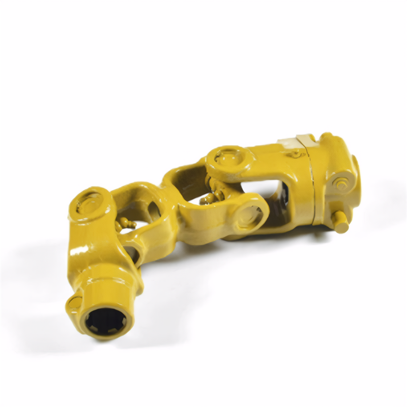
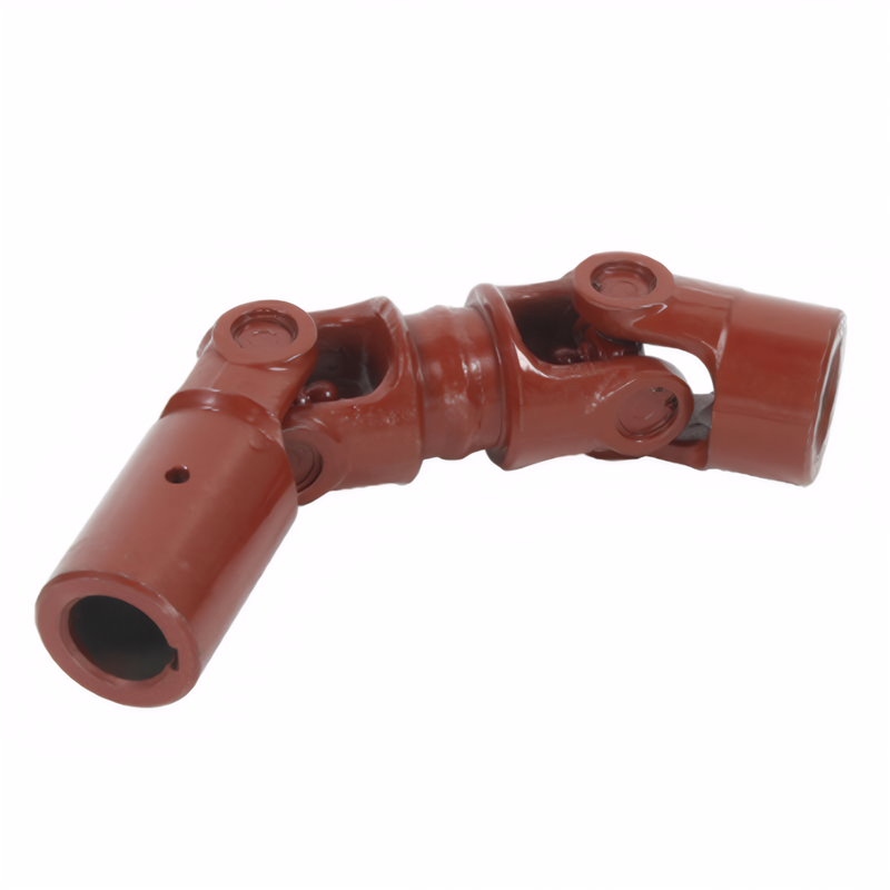
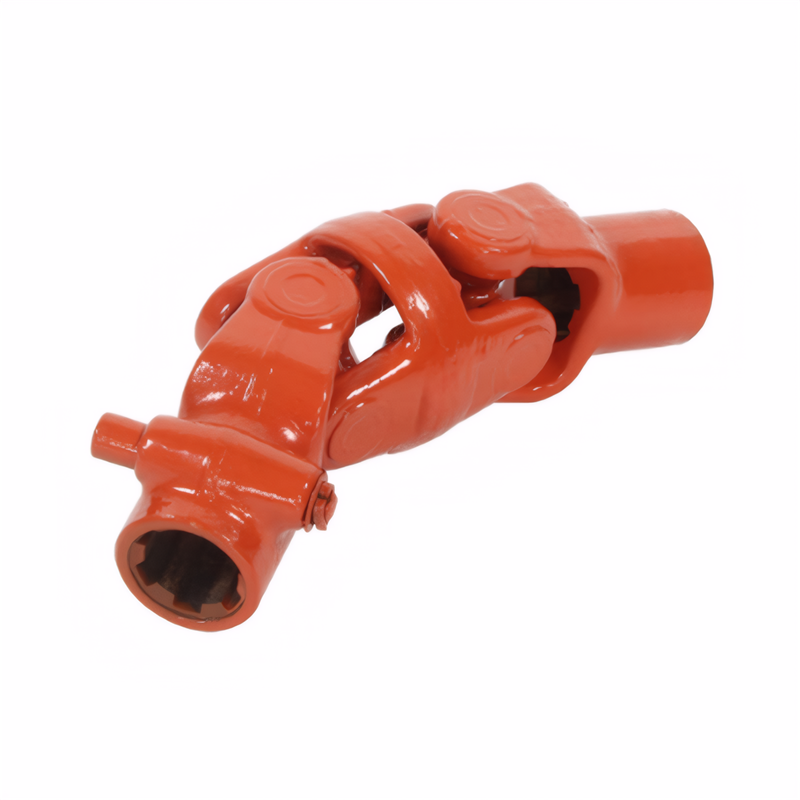
Mount the shaft securely on a balancing machine or V-blocks, ensuring it rotates freely without binding. For shafts with integrated components like universal joints, verify proper alignment and free movement of all articulating parts before proceeding with balance measurements.
Precision Measurement and Analysis Techniques
Employ vibration analysis equipment to detect imbalance by measuring the amplitude and frequency of vibrations during shaft rotation. Install accelerometers or velocity sensors at key points along the shaft to capture comprehensive vibration data. Rotate the shaft at multiple speeds to identify both static and dynamic imbalance conditions.
Use dial indicators to measure radial runout at critical locations including bearing journals and flange surfaces. Record measurements at 90-degree intervals around the shaft circumference to create a detailed profile of any geometric deviations. Compare these measurements against manufacturer tolerances to determine the severity of imbalance.
Analyze collected data using specialized software to calculate the exact magnitude and location of imbalance. The software will generate a correction plan specifying the amount of material to be added or removed and its precise angular position on the shaft. This analysis forms the basis for all subsequent correction steps.
Material Adjustment and Final Verification
Implement the correction plan by either adding balance weights or removing material from the shaft. For material addition, attach precision-machined weights at the specified locations using high-strength adhesive or mechanical fasteners. When removing material, use grinding or milling techniques to achieve the required mass reduction while maintaining surface integrity.
After making adjustments, re-mount the shaft on the balancing equipment and repeat the vibration analysis and runout measurements. Verify that all imbalance values now fall within acceptable tolerances specified by the vehicle manufacturer. Conduct multiple test runs at varying speeds to ensure consistent balance performance across the operating range.
Perform a final visual inspection to confirm that all correction work has been completed neatly without introducing new damage. Check that all balance weights are securely attached and that no metal shavings or debris remain on the shaft. Document the final balance readings and any corrective actions taken for future reference during maintenance cycles.
 The inspection method for the
 Symptoms of wear of the univer
 Analysis of the Causes of Abno
 The ability of the drive shaft
 简体中文
简体中文 English
