The design features of car drive shafts
Key Design Features of Passenger Car Drive Shafts
Passenger car drive shafts are engineered to balance performance, durability, and efficiency while adapting to diverse drivetrain configurations. Their design incorporates specialized components and structural innovations to meet the demands of modern automotive engineering.
Dynamic Angle Compensation Through Universal Joint Configurations
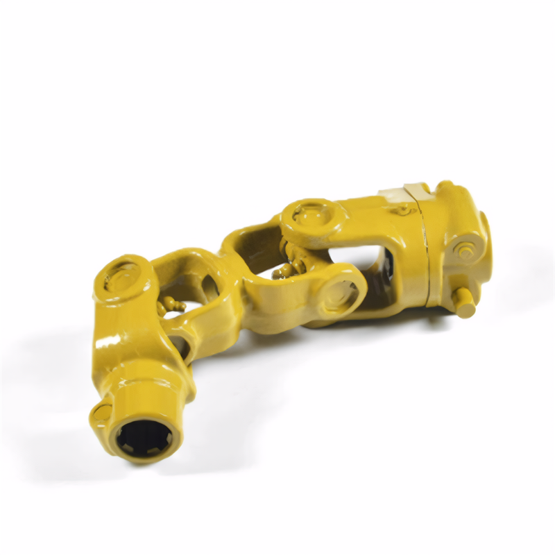
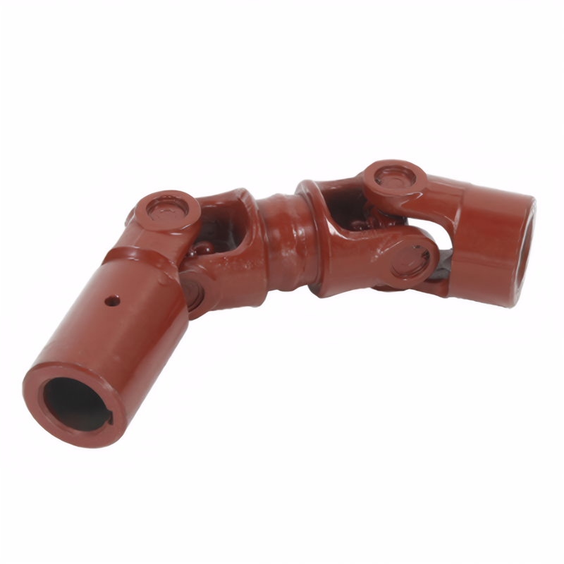
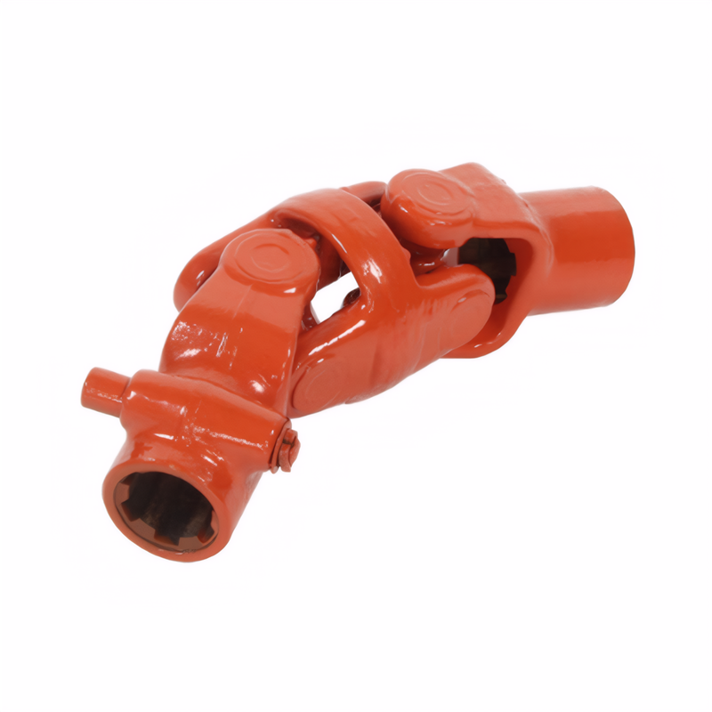
The core of drive shaft design lies in its ability to transmit torque across varying angles between the transmission and differential. In rear-wheel-drive (RWD) passenger cars, double-jointed universal joints are strategically positioned to maintain equal angular velocity transmission. Each universal joint assembly typically consists of a cross-shaped yoke with needle bearings at four points, allowing for 15-20 degrees of articulation while minimizing friction.
Precision Alignment for Vibration Reduction
To eliminate speed fluctuations caused by single universal joint operation, engineers implement a parallel-axis layout where both joints share identical operating angles. This configuration ensures that the second joint compensates for the non-uniform rotation generated by the first joint, maintaining consistent output speed across the drive shaft's operational range. The alignment accuracy requirement typically reaches ±0.5 degrees to prevent detectable vibrations during high-speed operation.
Adaptive Length Adjustment via Telescopic Mechanisms
Modern passenger cars incorporate telescopic drive shaft sections to accommodate suspension travel and chassis flex. The sliding joint design features splined inner and outer tubes with a interference fit, allowing for 20-30mm of axial movement.
Material Optimization for Wear Resistance
The splined interface undergoes specialized heat treatment to achieve a surface hardness of 45-50 HRC, while the core maintains sufficient ductility to prevent brittle fracture. Some designs integrate polymer liners between splines to reduce friction by 30-40% compared to traditional steel-on-steel contact. These liners also serve as noise dampers, absorbing impact energy during sudden load changes.
High-Speed Balancing and Structural Rigidity
Operating at rotational speeds exceeding 5,000 RPM in performance applications, drive shafts demand rigorous dynamic balancing. Manufacturers employ computer-controlled balancing machines to achieve imbalance levels below 30 g·cm, equivalent to removing a single grain of sand from the shaft's circumference.
Composite Construction for Weight Reduction
High-performance models utilize carbon fiber-reinforced polymer (CFRP) outer tubes paired with alloy steel inner shafts. This hybrid design reduces rotational inertia by 40% compared to all-steel constructions while maintaining torsional stiffness exceeding 800 Nm/deg. The CFRP layer also provides electromagnetic shielding, preventing interference with vehicle electronic systems. In critical stress areas, the shaft incorporates localized fiber reinforcement with a 60% higher density than standard sections.
 The inspection method for the
 Symptoms of wear of the univer
 Analysis of the Causes of Abno
 The ability of the drive shaft
 简体中文
简体中文 English
