

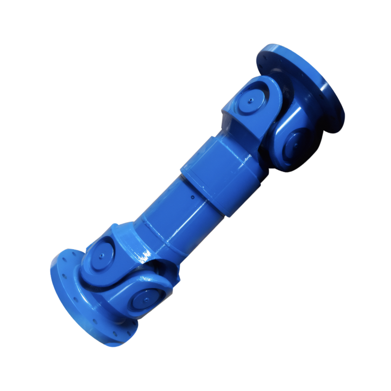
Check for deviation of the drive shaft after installation
Post-Installation Alignment Verification for Transmission Shafts
Initial Road Test Procedures
Controlled Environment Testing
Begin alignment verification by conducting tests on a smooth, level surface free from crowning or significant slope. Select a quiet road with minimal traffic to eliminate external variables during evaluation. Perform the following sequence:
- Accelerate gradually to 50 km/h while maintaining steady throttle input
- Note any immediate steering wheel pull or vehicle drift
- Release the steering wheel momentarily to observe natural vehicle trajectory
- Repeat the test in the opposite direction to confirm consistency
Document any deviations from straight-line travel, paying attention to whether the vehicle pulls consistently to one side or exhibits intermittent alignment issues. Perform multiple test cycles to establish reliable baseline data.
Dynamic Response Analysis
Evaluate transmission shaft performance during transient maneuvers:
- Execute gentle lane changes at 40-60 km/h
- Monitor for delayed driveline response or abnormal vibration during transitions
- Perform moderate acceleration bursts while maintaining straight-line travel
- Observe steering wheel behavior during throttle application and release
- Note any clunking sounds from the driveline during gear changes (manual transmissions)
These dynamic tests help identify misalignment issues that may not appear during steady-state driving conditions. Record the specific conditions under which any abnormalities occur.
Component-Level Inspection Points
Flange Connection Evaluation
Examine transmission shaft mounting flanges for proper alignment:
- Verify bolts are tightened to manufacturer specifications using a torque wrench
- Check for paint transfer or witness marks indicating movement between mating surfaces
- Inspect for cracks or deformation around bolt holes
- Measure the gap between flange faces using feeler gauges to ensure uniformity
- Confirm proper orientation of alignment marks (if present)
Misaligned flanges create angular misalignment in the transmission shaft, leading to vibration and premature component wear. Compare measurements to factory specifications whenever available.
Support Bearing Analysis
Review intermediate support bearings for proper installation:
- Check for even load distribution across the bearing surface
- Verify rubber mounts remain free from deformation or permanent set
- Inspect for abnormal heat generation after road testing
- Measure bearing endplay using dial indicators
- Confirm proper alignment with chassis reference points
Improperly installed support bearings alter the transmission shaft's operating angles, causing vibration that may manifest as steering pull. Document any out-of-specification measurements for further analysis.
Advanced Diagnostic Techniques
Laser Alignment Verification
For precision alignment verification:
- Use laser alignment tools to measure shaft angles relative to chassis reference lines
- Compare actual measurements to factory specifications for maximum angular deviation
- Check for parallelism between transmission output shaft and differential input shaft
- Evaluate compound angles at universal joint locations
- Document all measurements for comparison for future maintenance
This non-contact measurement method provides definitive data about transmission shaft alignment status. Pay particular attention to angles exceeding 1.5 degrees, which typically indicate misalignment requiring correction.
Vibration Spectrum Analysis
Employ diagnostic equipment to analyze driveline vibrations:
- Attach accelerometers to key driveline components
- Record vibration data across multiple speed ranges
- Identify dominant frequencies corresponding to specific components
- Compare amplitude readings to established baseline values
- Generate phase angle measurements to pinpoint vibration sources
This technique helps distinguish between alignment issues and other potential problems like unbalanced components or worn universal joints. Save all diagnostic reports for trend analysis over time.
Corrective Action Implementation
Adjustment Procedures
When misalignment is confirmed:
- Loosen transmission shaft mounting bolts while supporting the component
- Use hydraulic jacks or pry bars to make incremental adjustments
- Re-tighten bolts in proper sequence to manufacturer specifications
- Recheck alignment measurements after each adjustment
- Perform multiple road tests between adjustments to evaluate effectiveness
Document all adjustment attempts and their outcomes to establish the most effective correction method for the specific vehicle configuration.
Post-Correction Verification
After alignment adjustments:
- Conduct extended road tests covering various speed ranges and load conditions
- Re-inspect all mounting hardware for proper torque retention
- Verify no new noises or vibrations have been introduced
- Check for proper clearance between transmission shaft and surrounding components
- Confirm steering wheel remains centered during all driving conditions
Maintain detailed records of all corrective actions taken, including tools used and measurements recorded, to support future maintenance efforts and warranty claims if applicable.
 The structure of the middle su
 The connection method of the d
 The function of the splined sh
Check for deviation of the dri
The function of the splined sh
Check for deviation of the dri