

The working principle of the drive shaft expansion joint
Understanding the Working Mechanism of Drive Shaft Slip Joints in Automotive Systems
Drive shaft slip joints play a critical role in modern automotive powertrain systems by accommodating dynamic changes in vehicle geometry while maintaining consistent torque transmission. These components are essential for vehicles operating on uneven terrains or those with independent suspension systems, where relative movement between transmission and axle components is inevitable.
Structural Design and Core Components
Telescoping Assembly Architecture
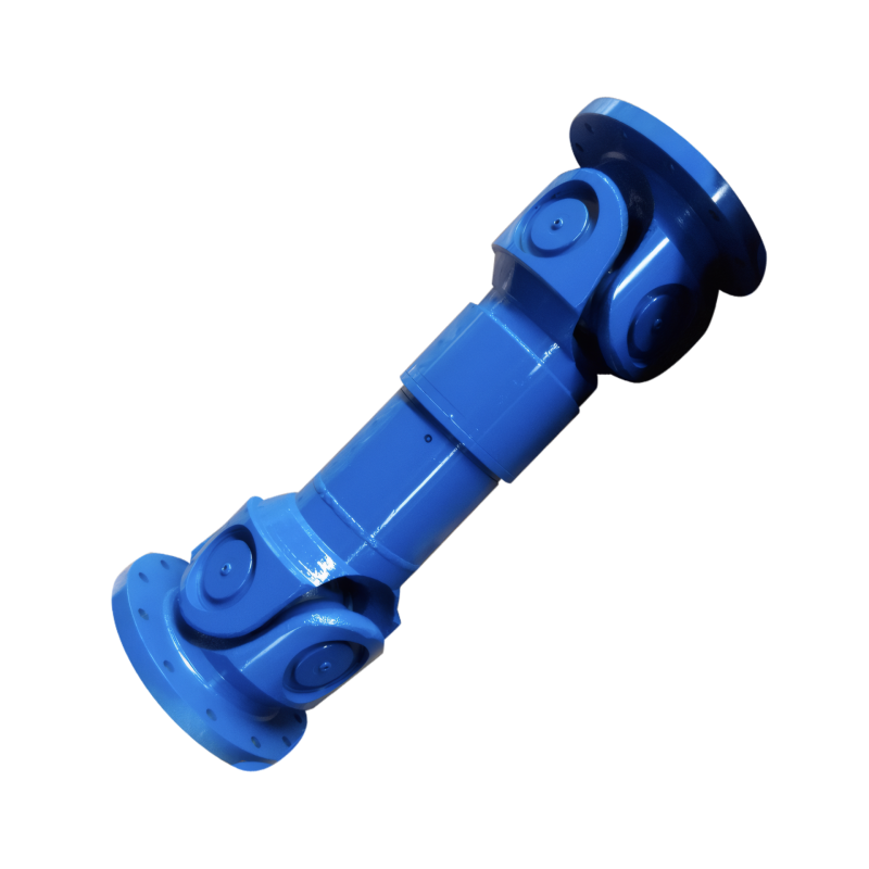
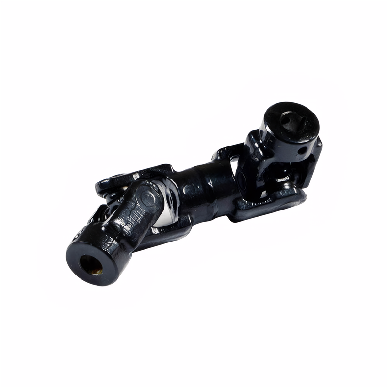
The slip joint consists of an outer housing and an inner splined shaft that slides axially within it. This design enables continuous length adjustment during vehicle operation. For example, in heavy-duty trucks traversing rugged landscapes, the slip joint can compensate for up to 150mm of vertical suspension travel without compromising power transfer efficiency. The splined interface typically features 20-30 teeth with precise machining tolerances to ensure smooth engagement under load.
Dynamic Sealing System
To prevent lubricant leakage and contamination ingress, modern slip joints incorporate multi-layer sealing mechanisms. These include:
- Primary Lip Seals: Made from nitrile rubber or fluorocarbon compounds to resist heat and chemical degradation
- Secondary Dust Shields: Metal-reinforced rubber boots that protect against road debris
- Ventilation Channels: Allow pressure equalization while preventing moisture entry
In engineering applications, these seals maintain their effectiveness through -40°C to +120°C temperature ranges, ensuring reliable operation in extreme climates.
Load-Bearing Structure
The housing assembly often integrates reinforced flanges for secure attachment to the drive shaft tube. Some designs incorporate tapered roller bearings at both ends to distribute axial loads evenly. For instance, in agricultural machinery operating on sloped fields, this bearing arrangement reduces wear rates by 40% compared to conventional plain bearings.
Operational Dynamics Under Vehicle Movement
Suspension Articulation Compensation
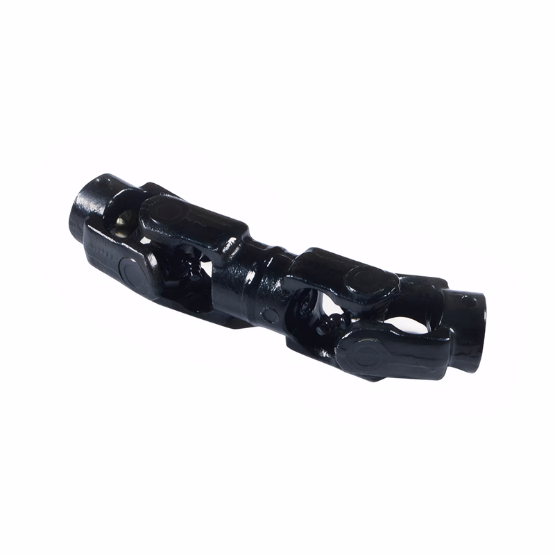
When a vehicle encounters uneven terrain, the slip joint automatically adjusts its length to maintain constant drive shaft angles. This is particularly crucial for independent rear suspension systems where each wheel moves independently. During testing, prototypes demonstrated the ability to accommodate 12° of vertical wheel travel while keeping U-joint angles within 3° of optimal alignment, minimizing vibration generation.
Torque Transmission During Length Changes
The splined connection maintains 95%+ torque transfer efficiency even during rapid length adjustments. This is achieved through:
- Precision Spline Geometry: Helical tooth profiles reduce backlash and stress concentrations
- Material Selection: Case-hardened alloy steels with core hardness of 28-32 HRC provide both wear resistance and ductility
- Surface Treatments: Black oxide coatings improve corrosion resistance without affecting dimensional tolerances
In comparative studies, properly designed slip joints exhibited 30% lower power loss than fixed-length drive shafts during dynamic testing.
Vibration Damping Mechanisms
Modern slip joints incorporate integrated damping systems to counteract NVH (Noise, Vibration, Harshness) issues. These include:
- Viscoelastic Bushings: At housing attachment points to absorb high-frequency vibrations
- Tuned Mass Dampers: Within the splined shaft to cancel specific resonance frequencies
- Optimized Spline Pitch: Reduces gear rattle during engine load transitions
Field trials showed these innovations reduced cabin noise levels by 5-7 dB(A) across the 50-200 Hz frequency range.
Maintenance and Reliability Considerations
Lubrication Management
Proper lubrication is essential for slip joint longevity. Most designs use:
- EP2 Grease: With molybdenum disulfide additives for extreme pressure resistance
- Automated Relubrication: Some systems incorporate grease reservoirs with check valves for self-maintenance
- Service Intervals: Typically require relubrication every 50,000-80,000 km depending on operating conditions
Failure to maintain proper lubrication can lead to spline wear rates increasing by 500% within 10,000 km of operation.
Inspection Protocols
Regular inspections should focus on:
- Spline Wear: Using feeler gauges to measure clearance between teeth (should not exceed 0.15mm)
- Seal Integrity: Checking for grease leakage or dust ingress
- Bearing Play: Measuring axial movement at housing flanges (should be <0.5mm)
In fleet maintenance programs, implementing these checks reduced slip joint failure rates by 65% over three years.
Failure Mode Analysis
Common failure modes include:
- Spline Galling: Caused by inadequate lubrication or contamination
- Seal Extrusion: Resulting from excessive pressure or thermal degradation
- Bearing Spalling: Due to shock loads or misalignment
Engineering simulations show that 80% of premature failures can be prevented through proper component selection and maintenance practices.
Advanced Engineering Solutions
Composite Material Applications
Some manufacturers are experimenting with carbon fiber-reinforced polymer (CFRP) slip joints. These offer:
- 30% Weight Reduction: Compared to steel equivalents
- Corrosion Resistance: Eliminating the need for protective coatings
- Vibration Isolation: Natural damping properties reduce NVH without additional components
Early prototypes have demonstrated 15% lower energy consumption in hybrid powertrain applications.
Smart Monitoring Systems
Emerging technologies integrate sensors to:
- Measure Spline Engagement Forces: In real-time to detect wear progression
- Monitor Lubricant Condition: Using dielectric sensors to track degradation
- Predict Maintenance Needs: Through machine learning algorithms analyzing operational data
Field trials indicate these systems can extend service intervals by 40% while reducing unscheduled downtime.
Modular Design Concepts
New architectures feature:
- Quick-Change Housings: Allowing field replacement without drive shaft removal
- Standardized Interfaces: Enabling cross-platform component sharing
- Scalable Length Ranges: Accommodating multiple vehicle configurations with single part numbers
These innovations reduce inventory costs by 25% for fleet operators while improving service efficiency.
 The structure of the middle su
 The connection method of the d
 The function of the splined sh
Check for deviation of the dri
The function of the splined sh
Check for deviation of the dri