 简体中文
简体中文 English

The structural features of the universal joint of the drive shaft
Structural Characteristics of Drive Shaft Universal Joints
Core Components and Their Functional Integration
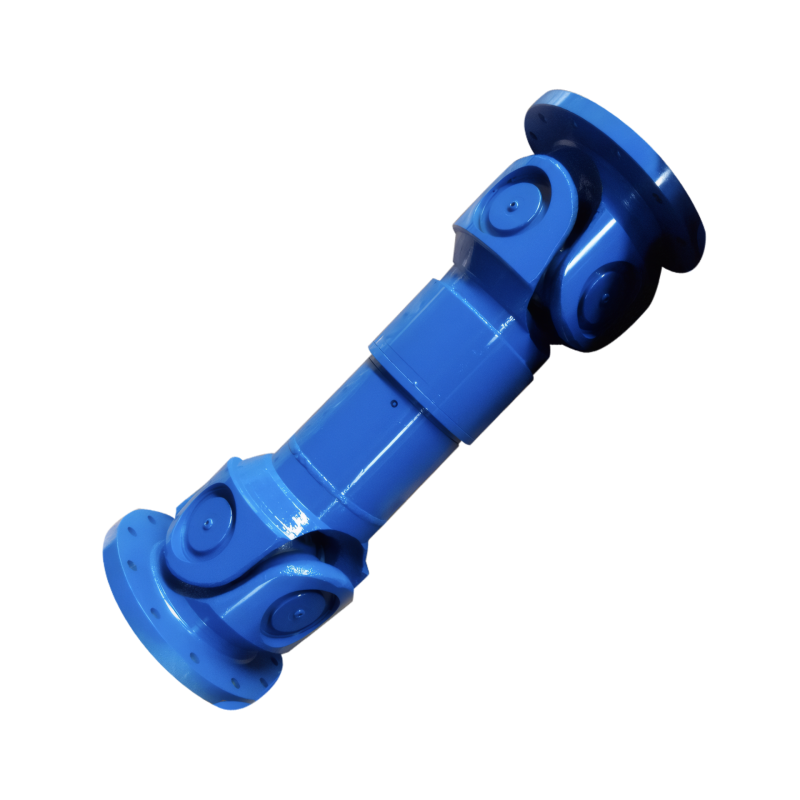
The universal joint in a drive shaft system serves as a critical connector enabling flexible power transmission between components with varying relative positions. Its core structure typically includes a cross-axis, bearing assemblies, and yoke forks. The cross-axis, often machined from high-strength alloy steel, acts as the rotational center. Each of its four trunnions houses needle bearings or roller bearings, which reduce friction and enable smooth angular movement. The yoke forks, welded to the drive shaft tube or transmission/differential flanges, form the mechanical interface for torque transfer.
In modern designs, the integration of these components has evolved to enhance durability. For instance, some universal joints adopt sealed bearing units filled with high-temperature grease, eliminating the need for periodic lubrication. Others incorporate precision-ground trunnions to minimize wear under high-torque conditions. These advancements address the fundamental challenge of maintaining stable power transmission while accommodating up to 20° of angular misalignment between connected shafts.
Angular Velocity Compensation Mechanisms
The universal joint's ability to compensate for angular velocity variations stems from its kinematic design. When a single universal joint operates at an angle, the output shaft experiences cyclical speed fluctuations relative to the input shaft. This phenomenon, known as "velocity fluctuation," is mathematically described by the equation:
Where:
- = Output angular velocity
- = Input angular velocity
- = Joint angle
- = Rotation angle of the input shaft
To mitigate this effect, automotive systems employ dual-universal joint configurations with precise geometric alignment. The two joints are positioned such that their yoke forks lie in the same plane, and the angles between each joint and the intermediate shaft are equal. This arrangement ensures that the velocity fluctuations of the first joint are canceled by the inverse fluctuations of the second, achieving near-constant angular velocity transmission.
Specialized Designs for Diverse Applications
Constant Velocity Joints (CV Joints)
For applications requiring zero velocity fluctuation, such as front-wheel-drive vehicles, constant velocity joints are employed. The most common type, the Rzeppa joint, uses six steel balls confined within a spherical housing. As the joint articulates, the balls follow grooves that maintain equal distances between the input and output shafts, ensuring true constant velocity transmission. This design supports angular movements up to 52° and axial displacements of ±50 mm, making it ideal for independent suspension systems.
Tripod Joints
Another CV joint variant, the tripod joint, features three roller bearings mounted on a spider assembly. These bearings engage with trapezoidal tracks on the outer housing, allowing for both angular and axial movement. Its compact structure and low friction make it suitable for drive shafts in transverse-engine layouts, where space constraints are significant.
Flexible Couplings
In industrial applications, flexible universal joints incorporate elastomeric elements between metal components. These couplings absorb vibrations and compensate for minor misalignments without introducing backlash. The rubber or polyurethane inserts act as dampers, reducing noise and extending component life in low-speed, high-torque environments.
Material Science and Manufacturing Innovations
The structural integrity of universal joints relies heavily on material selection and processing techniques. High-carbon chromium steel (e.g., AISI 52100) is commonly used for bearings due to its excellent hardness and fatigue resistance. For yoke forks, forged steel alloys like 4140 or 4340 provide the necessary strength-to-weight ratio. Advanced manufacturing processes, such as cold forging and precision CNC machining, ensure dimensional accuracy within ±0.05 mm, critical for maintaining proper bearing preload and joint longevity.
Surface treatments further enhance performance. Case hardening via induction heating creates a wear-resistant outer layer while maintaining a ductile core. Some designs incorporate diamond-like carbon (DLC) coatings on bearing surfaces, reducing friction by up to 40% compared to traditional steel-on-steel contacts. These innovations collectively enable universal joints to withstand peak torques exceeding 5,000 N·m while operating at temperatures ranging from -40°C to 150°C.
Dynamic Behavior Under Real-World Conditions
The structural design of universal joints must account for dynamic loads generated during vehicle operation. When a drive shaft rotates, centrifugal forces act on the cross-axis and bearings, increasing the effective load by a factor proportional to the square of the rotational speed. At 6,000 RPM, this can result in a 25% increase in bearing stress compared to static conditions.
Additionally, the joints experience alternating bending stresses as the vehicle traverses uneven terrain. Finite element analysis (FEA) studies reveal that stress concentrations occur at the fillet radii of trunnions and yoke forks. To address this, modern designs incorporate generous radii and stress-relief grooves, reducing peak stresses by up to 30%.
Vibration isolation is another critical consideration. The natural frequency of a drive shaft assembly with universal joints typically falls between 50–200 Hz, depending on length and stiffness. If this frequency aligns with engine harmonics or road-induced excitations, resonance can occur, leading to premature failure. Dampers integrated into the joint housing or intermediate shafts mitigate this risk by absorbing vibrational energy.
 Customized design of drive shafts for special vehicles
 The durability of the drive shaft for off-road vehicles
 Introduction to the structural strength of truck drive shaft
The layout of the drive shaft for a four-wheel drive vehicle
Introduction to the structural strength of truck drive shaft
The layout of the drive shaft for a four-wheel drive vehicle