 简体中文
简体中文 English

The installation direction of the universal joint of the drive shaft
Proper Installation Orientation for Drive Shaft Universal Joints
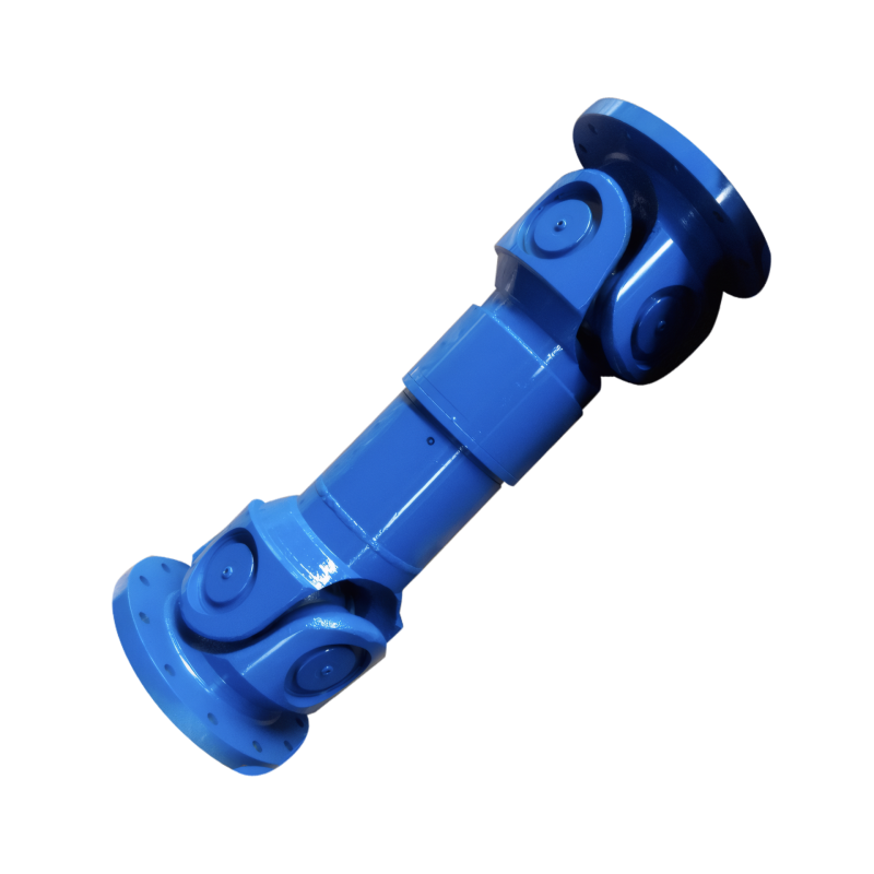
Universal joints (U-joints) serve as critical connection points in drive shaft systems, enabling variable-angle power transmission between non-aligned shafts. Correct installation orientation ensures smooth operation and prevents premature wear in automotive drivetrains.
Fundamental Orientation Principles
Universal joints must align with specific geometric relationships to maintain balanced power transmission. The two yokes connected by the cross-shaped joint must lie in the same plane when viewed from the side. This planar alignment prevents angular velocity fluctuations that cause vibration during rotation.
Angle Compensation Requirements
- Dual U-joint systems: When using two U-joints in a drive shaft assembly, their yoke planes must align precisely
- Single U-joint applications: The joint must compensate for the angle between input and output shafts while maintaining planar alignment
- Phase angle matching: In multi-piece drive shafts, adjacent U-joints require identical operating angles to prevent speed variation
Improper alignment creates harmonic vibrations that intensify with vehicle speed, leading to driveline fatigue and component failure.
Vehicle-Specific Installation Considerations
Different drivetrain configurations demand unique U-joint orientation approaches. Front-wheel-drive vehicles incorporate constant-velocity (CV) joints instead of traditional U-joints, while rear-wheel-drive systems rely on standard U-joint designs.
Drivetrain Type Variations
- Rear-wheel drive: U-joints connect transmission output shaft to differential input shaft
- Four-wheel drive: Transfer case output shafts require U-joints for front and rear drive shafts
- Commercial vehicles: Heavy-duty U-joints with larger cross-sections handle increased torque loads
Each configuration requires precise yoke alignment relative to the vehicle's centerline to maintain proper driveline angles.
Installation Process and Verification Methods
Proper U-joint installation involves careful handling and systematic verification. Begin by inspecting all components for wear or damage before assembly.
Step-by-Step Installation Guide
- Component preparation: Clean all mating surfaces and inspect bearing caps for cracks
- Yoke alignment: Position yokes so their planes form a straight line through the drive shaft center
- Fastener tightening: Torque retaining bolts to manufacturer specifications using a cross-pattern sequence
- Angle measurement: Verify operating angles match specifications using an inclinometer
After installation, perform a road test at increasing speeds while monitoring for vibration. Use a chassis ear or vibration analyzer to detect abnormal frequencies indicating misalignment.
Maintenance and Troubleshooting
Regular inspection prevents U-joint failure caused by wear or improper installation. Check for these warning signs during routine maintenance:
Common Failure Indicators
- Clicking noises: Worn needle bearings produce audible sounds during turns
- Vibration at speed: Misaligned U-joints create harmonic vibrations above 40 mph
- Grease leakage: Damaged seals allow contaminants to enter bearing assemblies
When replacing U-joints, always install new components in matched sets and verify angle compatibility with existing drivetrain components.
 Customized design of drive shafts for special vehicles
 The durability of the drive shaft for off-road vehicles
 Introduction to the structural strength of truck drive shaft
The layout of the drive shaft for a four-wheel drive vehicle
Introduction to the structural strength of truck drive shaft
The layout of the drive shaft for a four-wheel drive vehicle