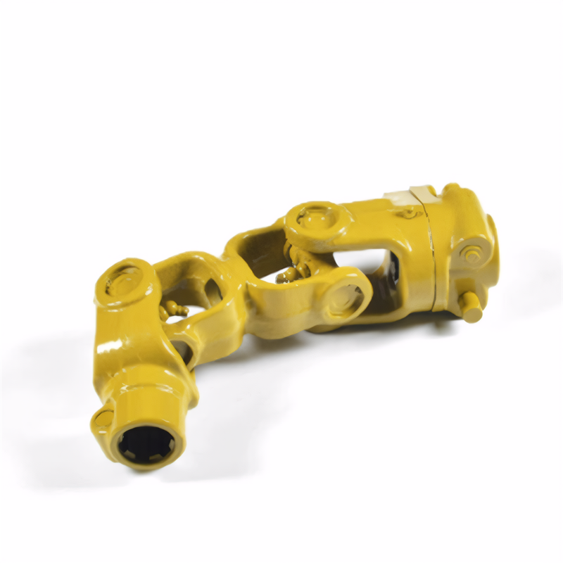
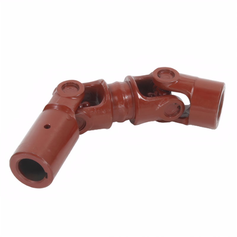
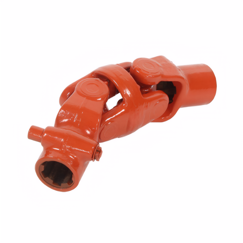
Alignment of the drive shaft with the gearbox
Drive Shaft and Transmission Alignment: Ensuring Smooth Power Transfer and Longevity
Proper alignment between the drive shaft and transmission is essential for minimizing vibrations, reducing wear on drivetrain components, and maintaining efficient power transfer. Misalignment can lead to premature failure of universal joints, seals, and bearings, as well as excessive noise and handling issues. Achieving accurate alignment requires attention to angular and parallel positioning, along with verification through measurement tools and operational testing. Below are key considerations for aligning these components during installation or maintenance.
Understanding Angular and Parallel Misalignment in Drivetrain Systems
Misalignment between the drive shaft and transmission typically manifests in two forms: angular and parallel. Angular misalignment occurs when the transmission’s output shaft and the drive shaft’s input yoke are not aligned along the same rotational axis, creating an angle that stresses U-joints and causes uneven wear. This often results from improper installation of transmission mounts, a bent drive shaft, or a mispositioned center support bearing in multi-piece systems.
Parallel misalignment, also known as lateral offset, happens when the drive shaft and transmission output are not perfectly concentric, shifting the shaft sideways relative to its intended path. This can stem from warped chassis components, loose mounting bolts, or incorrect spacing between the transmission and differential. Both types of misalignment generate vibrations that worsen with speed, leading to fatigue in drivetrain parts and potential failure if left unaddressed.
Techniques for Measuring and Adjusting Transmission Output Shaft Position
Accurate measurement of the transmission output shaft’s position relative to the drive shaft is critical for alignment. Start by ensuring the vehicle is on a level surface and the transmission is in neutral to allow free rotation of components. Use a straightedge or laser alignment tool to check the parallelism between the transmission output flange and the drive shaft’s input yoke. Any lateral gap or offset indicates parallel misalignment, which can often be corrected by adjusting transmission mounts or shimming components to restore concentricity.
For angular misalignment, measure the angle between the transmission output shaft and the drive shaft using an inclinometer or digital protractor. Minor angular discrepancies may be acceptable within manufacturer tolerances, but significant angles require repositioning the transmission or drive shaft. In some cases, bending the drive shaft slightly (if designed for adjustment) or realigning the center support bearing can resolve angular issues. Always consult service manuals for specific tolerance values to avoid over-correction.
Verifying Alignment Through Visual Inspection and Operational Testing
After making adjustments, visually inspect the alignment under good lighting to confirm no gaps or angles exist between mating components. Check that the drive shaft’s slip yoke or spline fits smoothly into the transmission output without binding or excessive play, as this indicates proper angular and parallel alignment. Rotate the drive shaft manually (if accessible) to ensure it moves freely without resistance, which suggests balanced U-joint angles and no misalignment-induced stress.
Operational testing is the final step to validate alignment. Take the vehicle for a short test drive, gradually increasing speed to monitor for vibrations or unusual noises. Pay attention to steering wheel oscillations or seat vibrations, which often signal residual misalignment. If issues persist, recheck measurements and adjustments, as even minor errors can cause noticeable problems at higher speeds. Repeat the alignment process until the drivetrain operates smoothly across all speed ranges.
Achieving precise alignment between the drive shaft and transmission hinges on addressing angular and parallel misalignment, using accurate measurement tools, and validating adjustments through visual and operational checks. Angular misalignment stresses U-joints and creates uneven wear, while parallel offset disrupts power transfer efficiency. Techniques like laser alignment or inclinometer readings help quantify misalignment, enabling targeted corrections such as shimming mounts or repositioning components. Final verification through manual rotation and road testing ensures alignment tolerances are met, preventing premature drivetrain failure and ensuring a comfortable driving experience. By prioritizing alignment accuracy, technicians and vehicle owners can extend the lifespan of critical drivetrain parts and maintain optimal performance.
 Method for detecting the stabi
 Reliability testing standard f
 Certification of environmental
 Transmission shaft safety perf
 简体中文
简体中文 English
