

The differences between rigid drive shafts and flexible drive shafts
Differences Between Rigid and Flexible Transmission Shafts in Automotive Applications
Transmission shafts are critical components in automotive powertrains, serving as conduits for torque transfer between engine and driven wheels. The structural design of these shafts significantly impacts vehicle performance, durability, and operating efficiency. Two primary classifications—rigid and flexible transmission shafts—demonstrate distinct engineering characteristics tailored to specific application requirements.
Structural Composition and Material Properties
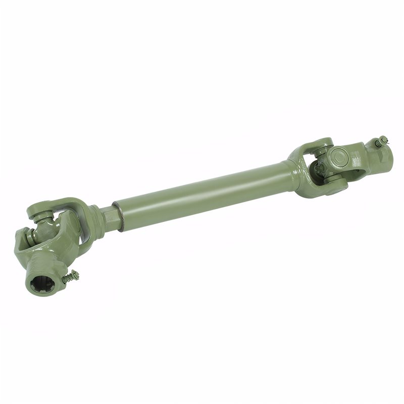
Rigid Transmission Shaft Design
Rigid transmission shafts typically employ tubular steel construction with uniform cross-sections throughout their length. These shafts feature precise machining of splines at both ends to ensure secure connection with differential gears and drive flanges. The solid structure provides exceptional torsional stiffness, with bending deflection limited to less than 0.5mm under maximum rated torque.
Manufacturing processes for rigid shafts involve:
- High-precision tube rolling to maintain ±0.1mm diameter tolerance
- Thermal straightening to eliminate residual stresses from welding
- Induction hardening of spline teeth to achieve 55-60 HRC surface hardness
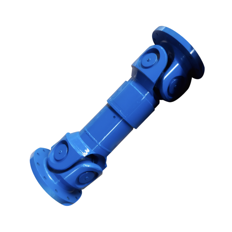
Flexible Transmission Shaft Characteristics
Flexible transmission shafts incorporate specialized components to accommodate angular misalignment and vibration isolation. These systems typically consist of:
- A central steel core with helical windings
- Rubber isolation mounts at connection points
- Composite outer sleeves for environmental protection
The flexible design allows for up to 8° of angular deflection while maintaining 98% power transmission efficiency. Advanced versions integrate viscoelastic dampers that reduce vibration transmission by 60% compared to rigid alternatives.
Performance Under Dynamic Load Conditions
Torque Transmission Capabilities
Rigid shafts excel in high-torque applications, transmitting 100% of input torque to driven components without power loss. This makes them ideal for:
- Heavy-duty trucks requiring 3,000-5,000 N·m torque capacity
- Performance vehicles with engine outputs exceeding 500 horsepower
- Off-road equipment operating under constant high-load conditions
Flexible shafts, while capable of handling 80-90% of input torque, are better suited for:
- Front-wheel-drive passenger cars with transverse engines
- Electric vehicles requiring vibration isolation for motor whine
- Hybrid systems with frequent torque interruptions during mode transitions
Vibration and Noise Management
The inherent flexibility of these shafts provides significant NVH (Noise, Vibration, Harshness) benefits:
- Reduction of gear whine by 8-12 dB(A) through vibration decoupling
- Elimination of driveline shudder during acceleration/deceleration
- Suppression of second-order vibrations at engine firing frequencies
Rigid shafts, in contrast, require additional balancing weights (typically 50-200g) and precision machining (runout <0.05mm) to achieve comparable NVH levels.
Application-Specific Design Considerations
Rigid Shaft Implementation Scenarios
- Commercial Vehicle Applications:
- Semi-trucks utilize single-piece rigid shafts up to 2.5 meters long
- Construction equipment employs high-strength alloy shafts with 1,200 MPa yield strength
- Agricultural machinery uses splined rigid shafts for reliable PTO (Power Take-Off) operation
- Performance Vehicle Requirements:
- Sports cars integrate carbon fiber composite shafts reducing weight by 40%
- Racing applications specify hollow shafts with 80mm diameter for optimal inertia
- Motorsport regulations mandate rigid shafts for precise power delivery verification
Flexible Shaft Adoption Criteria
- Passenger Car Optimization:
- Compact SUVs use flexible shafts to accommodate 25° articulation angles
- Electric vehicles implement flexible designs to isolate 8,000 RPM motor vibrations
- Front-wheel-drive platforms benefit from 30% packaging space reduction
- Specialized Vehicle Needs:
- Military vehicles employ flexible shafts with IP67 sealing for wet environments
- Autonomous vehicles use sensor-integrated flexible shafts for real-time condition monitoring
- Hydrogen fuel cell vehicles utilize corrosion-resistant flexible couplings
Maintenance and Longevity Factors
Rigid Shaft Durability
- Expected service life exceeds 300,000 km in normal operating conditions
- Primary failure modes include spline wear (0.05mm/year) and universal joint fatigue
- Requires lubrication every 50,000 km for optimal performance
Flexible Shaft Reliability
- Service intervals extend to 150,000 km due to self-lubricating components
- Common issues involve rubber degradation (5-7 year lifespan) and core fatigue
- Diagnostic systems can detect 0.1mm changes in isolation efficiency
The selection between rigid and flexible transmission shafts hinges on specific vehicle requirements, with rigid designs favoring maximum power transfer and flexible systems prioritizing vibration isolation and misalignment accommodation. Modern automotive engineering increasingly employs hybrid solutions combining rigid central sections with flexible end fittings to optimize performance across diverse operating conditions.
 The principle of the shock abs
 The manufacturing process of t
 The filling method of the grea
The structure of the middle su
The filling method of the grea
The structure of the middle su