The function of compensating for distance changes in the drive shaft
Compensation Mechanisms for Distance Variation in Drive Shafts
Drive shafts play a critical role in automotive powertrain systems by accommodating dynamic changes in distance between connected components during vehicle operation. This capability ensures consistent torque transmission despite suspension movement, steering inputs, and road irregularities.
Adaptive Length Adjustment Through Telescopic Design
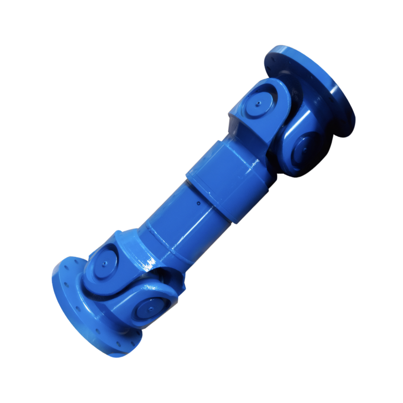
Modern drive shafts integrate telescopic sections to compensate for axial displacement caused by suspension travel. These sections typically employ splined shafts with sliding interfaces that maintain continuous engagement while allowing controlled length variation. The spline design distributes stress evenly across multiple teeth, preventing premature wear even under high torque loads.
Key Implementation Features
- Spline engagement length: Minimum 50mm to accommodate typical suspension movement
- Clearance tolerance: Maintained below 0.05mm to prevent rattling
- Lubrication system: Grease channels ensure consistent lubrication across sliding surfaces
- Material selection: High-strength alloy steels with surface hardening (HRC58-62) resist wear
This design enables drive shafts to maintain proper alignment and power transmission during full compression or extension of the vehicle's suspension system. The telescopic mechanism operates silently, with vibration damping materials integrated into the spline housing to minimize noise.
Universal Joint Angle Compensation
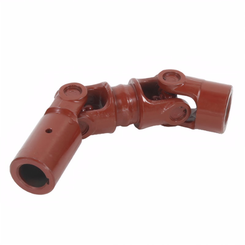
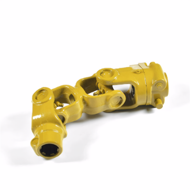
Drive shafts utilize universal joints (U-joints) to handle angular misalignment between connected components. These joints employ needle bearings trapped in a cross-shaped yoke, allowing rotation around two perpendicular axes. The design accommodates angular variations up to 30 degrees in automotive applications without significant power loss.
Dynamic Performance Characteristics
- Angular velocity variation: Kept below 2% through proper phasing of double U-joint configurations
- Bearing preload: Maintained between 5-15 N·m to prevent backlash
- Lubrication intervals: Extended to 100,000 km through sealed grease chambers
- Temperature tolerance: Operates effectively from -40°C to 120°C
In four-wheel-drive systems, constant velocity joints (CV joints) replace traditional U-joints at the wheel ends to eliminate speed fluctuations during steering maneuvers. These joints use ball bearings trapped between an inner race and outer housing to maintain equal angular velocity across all steering angles.
Flexible Coupling Systems for Vibration Isolation
To counteract torsional vibrations caused by engine pulsations and road inputs, drive shafts incorporate flexible couplings at key connection points. These couplings use elastomeric elements or torsionally soft steel springs to absorb and dissipate vibration energy.
Vibration Mitigation Strategies
- Natural frequency tuning: Couplings designed to operate outside engine firing frequency range (typically 150-250 Hz)
- Damping coefficient: Optimized between 500-1,500 N·s/m for passenger vehicles
- Temperature stability: Maintains damping performance across -30°C to 100°C
- Fatigue resistance: Withstands 10 million cycles at maximum torque load
Some advanced implementations use shape memory alloys that adjust damping characteristics based on operating temperature and load conditions. These materials provide adaptive vibration control without requiring electronic intervention.
Dynamic Balancing for High-Speed Operation
Drive shafts undergo precision balancing to eliminate rotational imbalances that could cause vibration or premature failure. Computer-controlled balancing machines achieve imbalance levels below 30 g·cm, equivalent to removing a single grain of sand from the shaft's circumference.
Balancing Process Parameters
- Operating speed range: Balanced up to 6,000 RPM to cover typical automotive applications
- Residual imbalance tolerance: Maintained below 0.05 mm/kg
- Correction methods: Drilling or welding weights applied to compensate for mass distribution
- Verification: Dynamic balancing verified through real-time vibration analysis during testing
This process ensures smooth operation even at high rotational speeds, preventing harmful vibrations that could damage connected components or degrade ride comfort. The balancing precision directly correlates with the drive shaft's service life and reliability.
 Customized design of drive shafts for special vehicles
 The durability of the drive shaft for off-road vehicles
 Introduction to the structural strength of truck drive shaft
 The layout of the drive shaft for a four-wheel drive vehicle
 简体中文
简体中文 English
