 简体中文
简体中文 English

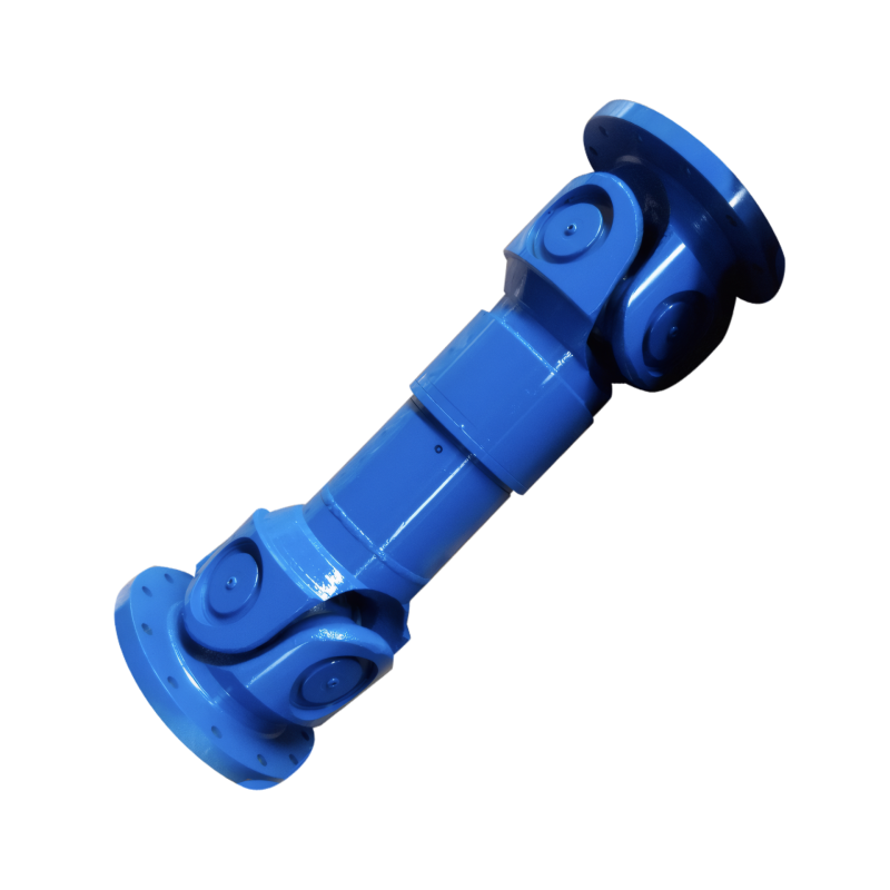
The filling method of the grease for the drive shaft
Effective Filling Methods for Transmission Shaft Grease in Mechanical Systems
Transmission shafts in automotive, industrial, and heavy machinery applications require precise lubrication to maintain operational efficiency and extend component lifespan. Proper grease filling methods ensure adequate lubrication while preventing over-lubrication issues like temperature rise and premature bearing failure. Understanding these techniques helps engineers optimize maintenance protocols for different operational environments.
Manual Filling Techniques for Precision Control
Manual grease filling remains the most common approach for automotive and small-scale industrial applications, offering direct control over lubrication quantity and distribution. This method uses specialized tools such as grease guns and manual pumps to deliver lubricant through designated ports. In automotive driveshaft maintenance, technicians employ grease guns to inject 2-3cc of NLGI #2 lithium-based grease into universal joint cross bearings every 5,000-8,000 kilometers. The process involves aligning the grease fitting with the bearing housing and applying steady pressure until fresh grease appears at the seals, indicating complete cavity replacement.
Tool Selection and Application Parameters
The choice of filling tool significantly impacts lubrication effectiveness. For high-precision applications like robotic transmission systems, pneumatic grease guns with adjustable pressure settings (typically 10-60 psi) enable controlled injection into compact bearing assemblies. In contrast, manual lever-action guns suit larger components like agricultural machinery driveshafts, where higher volume requirements (5-10cc per bearing) necessitate rapid lubricant delivery. Critical parameters include maintaining consistent injection pressure to avoid air entrapment and using needle-type nozzles for hard-to-reach areas in sliding spline couplings.
Automated Centralized Lubrication Systems
Large-scale industrial applications such as steel mill conveyor systems and mining equipment employ centralized lubrication to manage multiple lubrication points efficiently. These systems use electric pumps to distribute semi-fluid NLGI #00 grease through a network of stainless steel pipelines, ensuring simultaneous delivery to 20-50 bearing locations. The design incorporates progressive distributors that meter precise quantities (0.5-2cc per point) based on pre-programmed intervals, typically ranging from 8-24 hours depending on operational load.
System Design Considerations for Optimal Performance
Effective centralized lubrication requires careful calculation of pipeline diameter and length to maintain pressure consistency. For a 50-meter conveyor system with 30 lubrication points, 6mm diameter pipelines operating at 40 bar pressure ensure adequate flow rates without causing grease degradation. Temperature compensation mechanisms are critical in extreme environments; cryogenic applications (-40°C) demand heated pipelines to maintain grease viscosity, while high-temperature zones (120°C+) require heat-resistant perfluoroether-based lubricants. Monitoring systems with pressure sensors and flow meters provide real-time feedback, enabling predictive maintenance before lubrication failure occurs.
Semi-Automatic Filling with Grease Cups
Intermediate-scale applications like wind turbine yaw drives and marine propulsion systems utilize grease cups for semi-automated lubrication. These devices consist of a reservoir mounted adjacent to the bearing, with a threaded rod mechanism that progressively dispenses grease as the shaft rotates. A typical 200ml grease cup installed on a 100kW wind turbine generator bearing provides continuous lubrication for 3-6 months, depending on rotational speed (12-18 RPM). The cup requires manual reloading every maintenance cycle, with NLGI #1 calcium complex grease being preferred for its water resistance and mechanical stability.
Installation and Maintenance Protocols
Proper grease cup alignment is essential to prevent lubricant leakage. The reservoir must be mounted horizontally with the outlet port precisely aligned with the bearing feed channel, typically within ±2° tolerance. During installation, technicians prime the system by manually rotating the dispensing screw until fresh grease appears at the bearing outlet, ensuring immediate lubrication upon startup. Monthly inspections involve checking reservoir levels and cleaning exhaust valves to prevent clogging from hardened grease, particularly in dusty environments where contamination risk is elevated.
Specialized Filling for High-Speed Components
High-speed transmission shafts in electric vehicle drivetrains and aerospace applications demand specialized lubrication techniques to manage centrifugal forces and thermal loads. For components operating above 10,000 RPM, micro-dosing systems inject 0.1-0.5cc quantities of NLGI #1.5 synthetic grease directly into the bearing raceway using piezoelectric actuators. These devices synchronize injection pulses with shaft rotation, ensuring uniform lubricant distribution without creating excessive churning losses.
Thermal Management Strategies
Effective high-speed lubrication requires integrating cooling mechanisms with the filling process. Some advanced systems incorporate thermally conductive grease formulations containing aluminum oxide or boron nitride particles, which enhance heat dissipation from bearing contact zones. In electric vehicle e-axle applications, liquid-cooled bearing housings maintain operating temperatures below 80°C even under continuous 15,000 RPM operation, preventing grease breakdown and maintaining consistent lubrication performance.
 Customized design of drive shafts for special vehicles
 The durability of the drive shaft for off-road vehicles
 Introduction to the structural strength of truck drive shaft
The layout of the drive shaft for a four-wheel drive vehicle
Introduction to the structural strength of truck drive shaft
The layout of the drive shaft for a four-wheel drive vehicle