 简体中文
简体中文 English

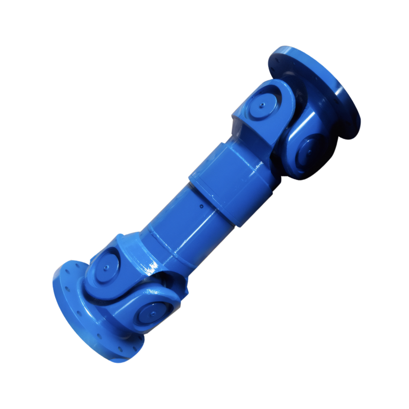
The working principle of a constant-speed drive shaft
Understanding the Operating Principle of Constant Velocity Drive Shafts
Constant velocity drive shafts play a critical role in automotive power transmission systems, ensuring smooth and efficient transfer of torque from the transmission to the driven wheels while accommodating angular variations between components.
Core Components and Their Functions
Outer Raceway and Star-Shaped Inner Race
The fundamental structure of a constant velocity joint, commonly the Rzeppa type, consists of an outer raceway and a star-shaped inner race. The outer raceway connects to the driven component (typically the wheel hub), while the inner race attaches to the transmission output shaft. The star-shaped inner race features six curved grooves that house six precision-ground steel balls. These balls are held in a spherical cage that maintains their relative positions during operation.
Ball and Cage Assembly
The ball and cage assembly serves as the torque transmission element. When the drive shaft rotates, the steel balls roll along the grooves in both the inner and outer races. The cage ensures the balls remain equally spaced, distributing the load uniformly across all six balls. This design enables the joint to transmit torque efficiently while maintaining constant velocity between input and output shafts, even at significant operating angles.
Mechanism of Constant Velocity Transmission
Angular Compensation Principle
The key innovation of constant velocity joints lies in their ability to maintain equal angular velocities between input and output shafts regardless of the operating angle. This is achieved through precise geometric alignment of the ball tracks. The center of each steel ball always lies on the angle bisector plane between the input and output shaft axes. This geometric relationship ensures that the instantaneous rotational speeds of both shafts remain synchronized throughout the joint's range of motion.
Force Transmission Path
During operation, torque enters through the star-shaped inner race and is transferred to the steel balls via the curved grooves. The balls then roll along the matching grooves in the outer raceway, transmitting the rotational force to the driven component. The spherical cage maintains proper ball positioning while allowing for smooth angular movement. This arrangement enables the joint to compensate for steering angles (up to 47° in automotive applications) without introducing speed variations or vibration.
Performance Characteristics and Advantages
High-Efficiency Power Transfer
Constant velocity joints demonstrate exceptional mechanical efficiency, typically exceeding 98% torque transmission capability. This high efficiency results from the rolling contact between steel balls and raceway grooves, which minimizes frictional losses compared to sliding contact joints. The design also reduces heat generation during operation, contributing to improved component longevity.
Vibration Damping and Noise Reduction
The precise alignment of components and uniform load distribution inherent in constant velocity joint design significantly reduce vibration and noise levels. The spherical cage acts as a natural vibration damper, absorbing minor misalignments and preventing the transmission of operational stresses to connected components. This characteristic makes these joints particularly suitable for front-wheel-drive and all-wheel-drive vehicles where smooth power delivery is essential for driver comfort.
Application Considerations in Vehicle Systems
Integration with Drive Shaft Assemblies
In automotive applications, constant velocity joints are typically incorporated into tubular drive shafts. These assemblies often feature two joints per shaft - one at each end - to accommodate the angular movements of both the transmission output and the driven wheel hub. The joints are protected by rubber boots filled with grease to maintain lubrication and prevent contamination from road debris.
Maintenance and Service Life
Proper maintenance of constant velocity joints involves regular inspection of the protective boots for cracks or leaks, as compromised seals can lead to premature joint failure. When functioning correctly, these joints demonstrate exceptional durability, with service lives often exceeding 150,000 miles (240,000 kilometers) in normal driving conditions. The absence of sliding friction surfaces contributes to their extended operational life compared to traditional universal joints.
 Customized design of drive shafts for special vehicles
 The durability of the drive shaft for off-road vehicles
 Introduction to the structural strength of truck drive shaft
The layout of the drive shaft for a four-wheel drive vehicle
Introduction to the structural strength of truck drive shaft
The layout of the drive shaft for a four-wheel drive vehicle