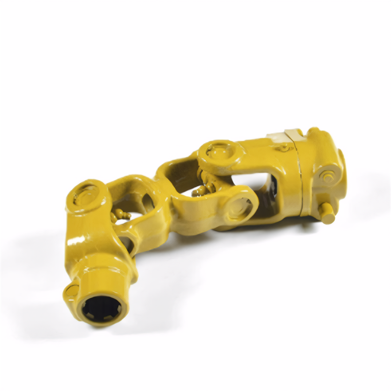
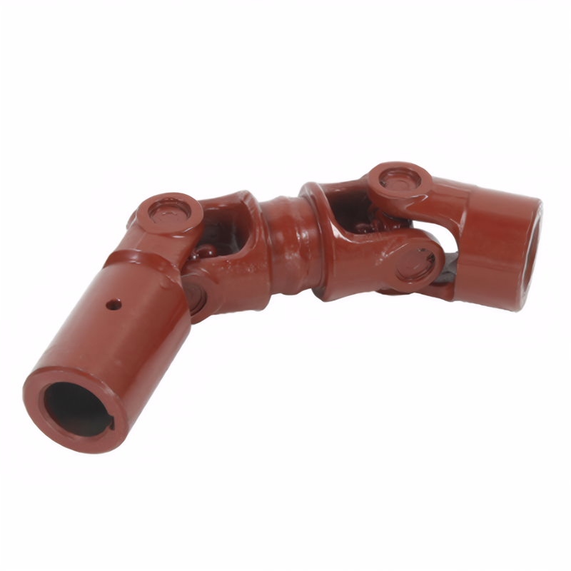
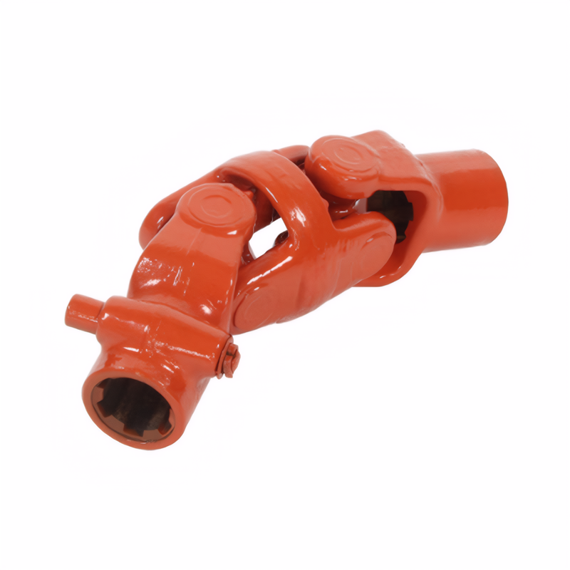
The process of balance correction for drive shafts
Transmission Shaft Balancing Correction Process: A Comprehensive Guide
Initial Inspection and Preparation
Before initiating balancing correction, a thorough inspection of the transmission shaft is essential. This involves checking for visible damage such as cracks, corrosion, or excessive wear on the shaft body and connecting components. Using precision tools like dial indicators and micrometers, technicians measure the shaft’s straightness and concentricity to identify deviations from standard specifications. For example, a shaft with a radial runout exceeding 0.5mm may require straightening before balancing. Cleaning the shaft surface is equally critical, as dirt, oil, or rust can interfere with measurement accuracy. Specialized cleaning agents and brushes are used to remove contaminants, ensuring reliable data collection during subsequent steps.
Static and Dynamic Balancing Techniques
Static balancing addresses mass distribution along a single plane, typically for shorter shafts or components with minimal rotational speed requirements. The shaft is placed on low-friction supports, and a dial indicator measures deflection. If imbalance is detected, weights are added or removed at specific locations to align the shaft’s center of mass with its rotational axis. For instance, a 10g imbalance might be corrected by welding a 10g counterweight at a calculated angle.
Dynamic balancing, which is more common for high-speed transmission shafts, involves correcting mass distribution across multiple planes. The shaft is mounted on a dynamic balancing machine, which spins it at operational speeds while sensors detect vibration amplitudes and phases. Advanced software analyzes the data to pinpoint imbalance locations and magnitudes. A two-plane balancing example might involve adding 8g of weight at 120° on the front plane and 5g at 240° on the rear plane to achieve equilibrium. This method is particularly effective for reducing noise and vibration in automotive drivetrains and industrial machinery.
Precision Adjustment Methods
Once imbalance data is obtained, precise adjustment methods are employed. For minor imbalances, drill-and-fill techniques are often used. A small hole is drilled at the imbalance location, and material (e.g., lead or epoxy) is added to counteract the offset. This method is suitable for shafts with thin walls or limited space for external weights.
In cases of significant imbalance, machining or grinding may be necessary. A computer-controlled milling machine removes material from the shaft’s surface at predetermined locations, ensuring minimal impact on structural integrity. For example, a 0.2mm layer might be ground off a 50mm-diameter shaft to correct a 15g imbalance. Advanced systems use laser ablation for non-contact material removal, offering higher precision and reducing the risk of thermal damage.
Verification and Quality Control
After adjustments, the shaft undergoes rigorous verification. A second dynamic balancing test confirms that imbalance levels meet industry standards, such as ISO 1940-1 Grade G2.5 for automotive components. Vibration analysis tools, including accelerometers and spectrum analyzers, are used to detect residual vibrations. If frequencies outside the acceptable range are identified, the balancing process is repeated until compliance is achieved.
Quality control also involves checking the shaft’s geometric tolerances post-balancing. Laser alignment systems ensure that the shaft’s rotational axis aligns with the drivetrain’s centerline, preventing misalignment-induced wear. Additionally, non-destructive testing methods like ultrasonic inspection verify the absence of internal defects that could compromise performance. These steps guarantee that the balanced shaft operates reliably under real-world conditions, extending its service life and enhancing overall system efficiency.
 Method for detecting the stabi
 Reliability testing standard f
 Certification of environmental
 Transmission shaft safety perf
 简体中文
简体中文 English
