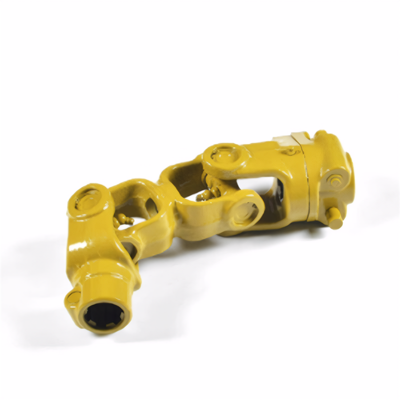
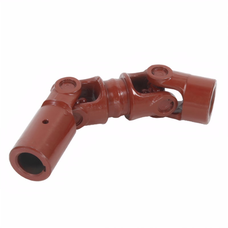
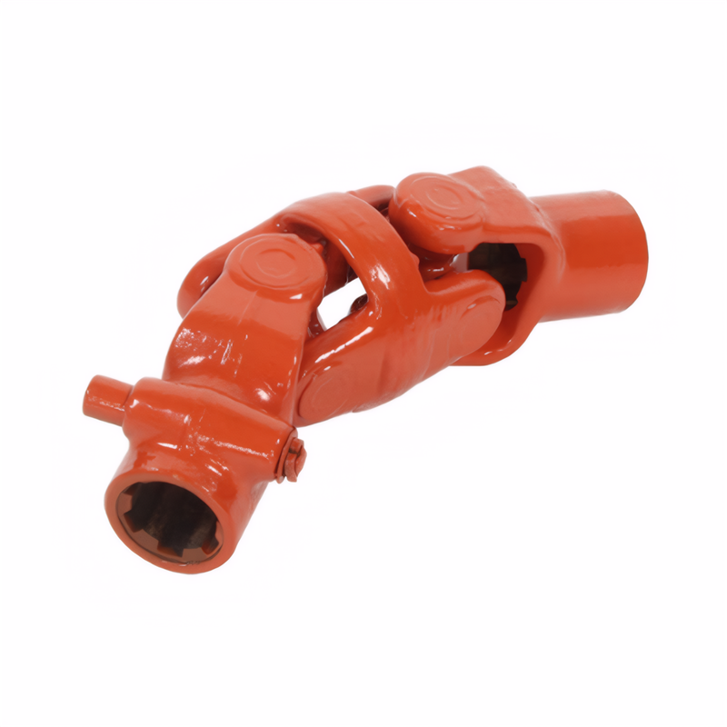
The characteristics of the forging process of the drive shaft
Fundamental Principles of Forging Technology for Transmission Shafts
Forging processes for transmission shafts are designed to optimize material properties and geometric precision through controlled plastic deformation. The core advantage lies in refining the metal's grain structure, which enhances mechanical performance by aligning crystal orientations along the shaft's stress axis. For instance, in automotive applications, 40Cr alloy steel subjected to die forging exhibits a 30–40% increase in fatigue resistance compared to cast counterparts due to its homogenized microstructure.
Grain Structure Optimization Through Controlled Deformation
The forging process involves multiple deformation stages that progressively refine the metal's internal structure. During hot forging, steel billets heated to 1,150–1,250°C undergo axial compression and radial extrusion in closed dies, eliminating internal voids and segregations. This results in a uniform distribution of ferrite and pearlite phases, critical for withstanding torsional loads in heavy-duty truck drivetrains.
Advanced techniques like radial forging further enhance material properties by applying synchronized impacts from multiple dies. This method produces shafts with a 50% reduction in cross-sectional area variation, ensuring consistent torque transmission in wind turbine gearboxes. The process also induces work hardening in surface layers, increasing wear resistance by 2–3 times compared to machined surfaces.
Precision Forming with Minimal Material Waste
Die forging enables near-net-shape production of complex shaft geometries, reducing machining allowances to 1–2 mm from traditional 5–8 mm. This is achieved through pre-form dies that distribute material efficiently before final shaping. For example, in the manufacturing of agricultural machinery driveshafts, this approach cuts raw material consumption by 18% while maintaining dimensional tolerances of ±0.1 mm.
Closed-die forging with split molds allows for intricate internal features, such as spline teeth and oil passages, to be formed simultaneously. This integration reduces secondary operations by 60% in electric vehicle propeller shaft production, where hollow tubular designs with 0.5 mm wall thickness require precise material flow control. The use of computer-aided engineering (CAE) simulations ensures optimal flash formation, minimizing post-forging trimming work.
Process Parameters Influencing Shaft Performance
The mechanical properties of forged transmission shafts are directly tied to critical process variables, including heating temperature, deformation rate, and cooling methods. These parameters must be carefully calibrated to prevent defects like overheating, incomplete forging penetration, or residual stress accumulation.
Temperature Management During Heating Stages
Heating systems for shaft forging typically employ medium-frequency induction furnaces capable of reaching 1,250°C within 120 seconds. Precise temperature control is essential to avoid grain coarsening above the critical transformation point. For 42CrMo4 alloy steel, maintaining a forging temperature range of 1,180–1,220°C ensures optimal ductility while preventing decarburization, which could reduce surface hardness by up to 30%.
In automotive constant velocity joint (CVJ) shaft production, multi-stage heating profiles are used to accommodate different section thicknesses. Thinner sections receive localized pre-heating to prevent thermal shock, while thicker hub areas undergo slower ramp-up rates to ensure uniform temperature distribution. This approach reduces scrap rates from thermal cracking by 75% in high-volume manufacturing lines.
Deformation Rate Control for Structural Integrity
The speed of metal flow during forging impacts both microstructure development and dimensional accuracy. For large-diameter marine propeller shafts, hydraulic press forging at 0.5–2 mm/s deformation rates produces superior grain alignment compared to faster hammer forging methods. Slow deformation allows for complete dynamic recrystallization, resulting in a 20% improvement in low-cycle fatigue life under oscillating loads.
In contrast, high-speed forging at 10–20 mm/s is preferred for small-diameter automotive driveshafts, where rapid deformation minimizes oxidation and scale formation. This method achieves surface finish ratings of Ra 1.6 μm without additional machining, reducing production costs by 15% in mass-market vehicle applications.
Quality Assurance Systems in Shaft Forging
Modern forging facilities implement multi-layered quality control protocols to ensure compliance with automotive and aerospace standards. These systems integrate real-time monitoring technologies with statistical process control (SPC) methods to detect deviations early in production.
Non-Destructive Testing for Internal Defects
Ultrasonic testing (UT) is the primary method for detecting subsurface flaws in forged shafts. Phased array UT systems with 64-element transducers can identify 0.5 mm-diameter voids at depths exceeding 200 mm, meeting the stringent requirements of ISO 10893-3 standards. This technology is critical for validating the integrity of wind turbine main shafts, where undetected defects could lead to catastrophic failure under 2 MN·m torque loads.
Magnetic particle inspection (MPI) complements UT by detecting surface cracks as small as 0.1 mm in length. Automated MPI lines using fluorescent penetrants achieve inspection speeds of 120 components per hour, with false positive rates below 0.2%. This level of precision is essential for ensuring the reliability of automotive differential shafts operating in corrosive environments.
Dimensional Validation Through Laser Scanning
Post-forging dimensional checks employ blue-light laser scanners capable of capturing 1.2 million measurement points per second. These systems generate 3D models with ±0.02 mm accuracy, enabling real-time comparison against CAD designs. In the production of electric vehicle driveshafts, this technology reduces rework rates by 90% by identifying dimensional drift in forming dies before it affects multiple production batches.
Coordinate measuring machines (CMMs) with 5-axis probing systems provide additional validation for critical features like spline profiles and bearing journals. Touch-trigger probes with 0.1 μm resolution ensure that gear teeth meet AGMA 2000-A88 tolerance specifications, preventing noise and vibration issues in transmission systems.
 Method for detecting the stabi
 Reliability testing standard f
 Certification of environmental
 Transmission shaft safety perf
 简体中文
简体中文 English
