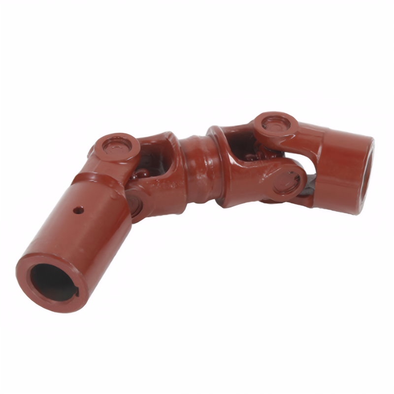
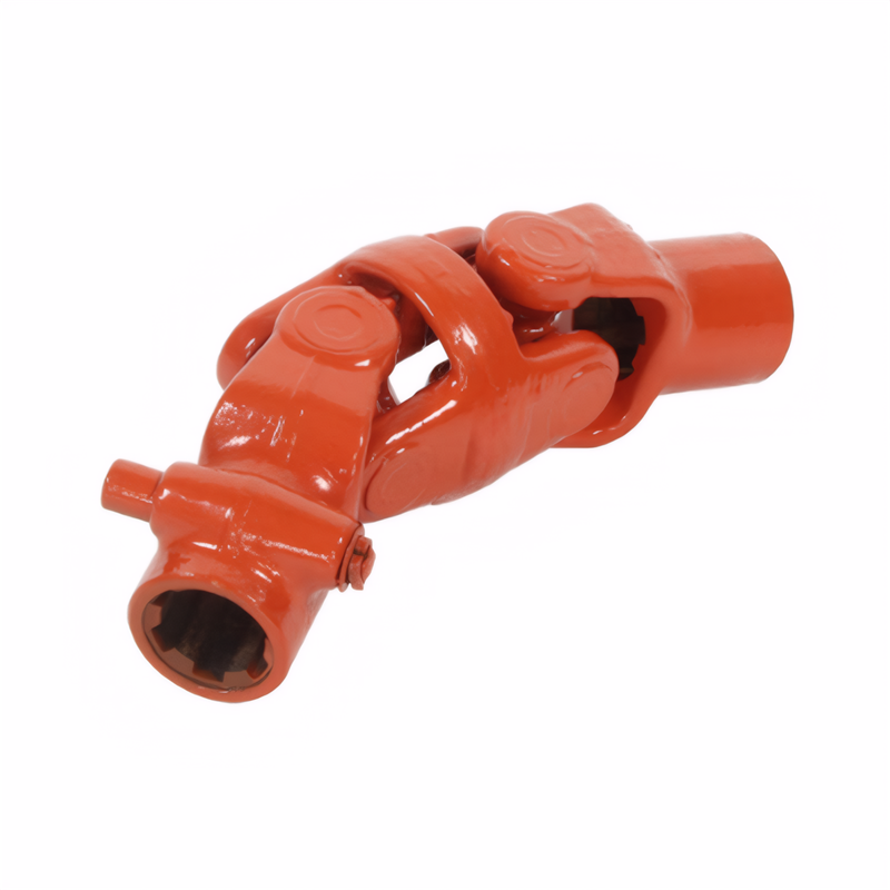
The parallelism requirements for the flange of the drive shaft
Parallelism Requirements for Transmission Shaft Flanges
General Parallelism Tolerance Standards
Industry - Wide Baseline Rules
In most industrial applications, the parallelism deviation of transmission shaft flanges should not exceed 1.5‰ of the flange's outer diameter, and the absolute maximum deviation is capped at 2 mm. This means that for a flange with an outer diameter of 1000 mm, the maximum allowable parallelism deviation is 1.5 mm (1000 mm × 1.5‰ = 1.5 mm), but it cannot exceed 2 mm under any circumstances. These standards are designed to ensure a proper fit and seal between the flanges, preventing issues such as leakage and uneven load distribution.
Significance of Adhering to Tolerances
Maintaining the specified parallelism tolerances is crucial for the overall performance of the transmission system. If the parallelism deviation is too large, it can lead to misalignment of the transmission shaft, causing increased friction and wear on the bearings and other components. This, in turn, can result in reduced efficiency, increased energy consumption, and a shorter lifespan of the equipment. Additionally, improper parallelism can cause vibration and noise during operation, affecting the comfort and safety of the working environment.
Parallelism Requirements for Specific Applications
High - Speed Rotating Equipment
For transmission shafts connected to high - speed rotating equipment, such as turbines or high - speed compressors, the parallelism requirements are even more stringent. In general, when the rotational speed of the equipment is between 3000 and 6000 revolutions per minute (r/min), the parallelism deviation should be ≤ 0.15 mm, and the coaxiality deviation should be ≤ 0.5 mm. When the rotational speed exceeds 6000 r/min, the parallelism deviation must be further reduced to ≤ 0.10 mm, and the coaxiality deviation to ≤ 0.2 mm. These strict requirements are necessary to minimize the dynamic imbalance and vibration generated during high - speed operation, ensuring the stable and reliable performance of the equipment.
Heavy - Duty Transmission Systems
In heavy - duty transmission systems, such as those used in mining or construction equipment, the parallelism of the transmission shaft flanges also plays a vital role. Although the rotational speeds may not be as high as in some industrial applications, the large loads and harsh operating conditions put significant stress on the components. Therefore, the parallelism deviation should still be kept within the industry - standard limits to prevent premature failure of the transmission shaft and related parts. For example, in a large - scale mining conveyor system, if the parallelism of the transmission shaft flanges is not properly maintained, it can lead to uneven power transmission, causing some sections of the conveyor to overwork and others to underutilize, resulting in increased maintenance costs and reduced productivity.
Inspection and Adjustment Methods for Parallelism
Inspection Techniques
There are several methods for inspecting the parallelism of transmission shaft flanges. One common method is to use a level gauge. Place the level gauge on the first flange and record the reading. Then, move the level gauge to the second flange and compare the readings. The difference between the two readings should be within the allowable parallelism deviation range. Another method is to use a dial indicator. Mount the dial indicator on a fixed base and position its probe against one of the flanges. Rotate the transmission shaft slowly and observe the movement of the dial indicator needle. The maximum variation in the readings indicates the parallelism deviation of the flanges.
Adjustment Procedures
If the parallelism deviation is found to be outside the acceptable range during inspection, adjustment is necessary. One way to adjust the parallelism is to use shims. Place shims of appropriate thickness between the flange and the mating surface to change the relative position of the flanges and achieve the desired parallelism. Another method is to use a hydraulic or mechanical jack to apply force to the flanges and adjust their position. However, this method requires careful operation to avoid over - stressing the components. After adjustment, re - inspect the parallelism to ensure that it meets the requirements.
 Method for detecting the stabi
 Reliability testing standard f
 Certification of environmental
 Transmission shaft safety perf
 简体中文
简体中文 English
